
User manual


INSTALLATION and OPERATING MANUAL FLARM-NAV Display and Navigation System
Version 1.13 Page 7 of 25 January 2012
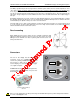
Port A: FLARM Data In
The eight-pin RJ45 Power/Data socket accepts an eight-pin connector (if necessary, a six-pin connector)
that is locked in place. The pin connections are largely in-line with those set out in IGC GNSS FR
Specifications
1
, so that the same cables may be used both in the air and on the ground, as used for modern
IGC-compatible flight data recorders. The key to the connections is defined by the sequence from left to
right, not the numbering
2
:
Port A (FLARM Data In) pin assignments
1. +6 to +26 VDC (recommended +12 VDC), linked with Pin 2 inside the unit
2. +6 to +26 VDC (recommended +12 VDC), linked with Pin 1 inside the unit
3. 1 wire Dallas interface, for future expansion
4. GND, with Pin 7 and 8 linked to the unit
5. Rx In = FLARM transmits data and FLARM-NAV receives it.
6. Tx Out = FLARM Receives data and FLARM-NAV Transmits it.
7. GND ('negative'), linked with Pin 8 inside the unit
8. GND ('negative'), linked with Pin 7 inside the unit
FLARM-NAV is powered through either port but at least pins 1&2 and 7&8 must be connected. RS 232 data
is received at 19.2kb from the FLARM device, make sure the baud speed in FLARM is set to 19.2kb (default
in OzFLARM and MiniOz units).
When connecting from OzFLARM or MiniOz or other FLARM devices please ensure correct polarity of the
power and data wires. Your FLARM-NAV display is supplied with a pre wired loom, however, other FLARM
compatible devices might require different connections. If the power and ground are reversed there should
be no damage to the unit, it just will not work but has reverse protection. If power is applied to the RS 232
lines permanent damage will occur to this port.
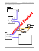
Port B: FLARM Data Out
An 8-pole connector may be inserted in the 8-pole RJ45 socket on the bottom looking from the rear. The
connections to the pins are the same as for Pins 1 and 8 described above. This socket is intended for use by
third party applications like glide computers (e.g. Altair from Triadis Engineering, see www.rf-
developments.com), by PDA’s or to a second FLARM-NAV in a two-seater configuration. This port basically
mimics the FLARM data coming in. If set to logger in the setup page then it will talk to a logger for
downloading IGC files etc.
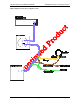
Port B (FLARM data out) pin assignments
1. +6 to +26 VDC (recommended +12 VDC), linked with Pin 2 inside the unit
2. +6 to +26 VDC (recommended +12 VDC), linked with Pin 1 inside the unit
3. Speaker out +
4. GND, with Pin 7 and 8 linked inside the unit
5. Tx = transmits data
6. Rx = receives data
7. GND ('negative'), linked with Pin 8 inside the unit
8. GND ('negative'), linked with Pin 7 inside the unit
In normal configuration with OzFLARM, Pin 5 transmits the most important NMEA-0183 Version 2.0
compatible GPGGA and GPRMC codes at a fixed data rate of 19.2KB.
1
Chapter 2.7.2.2.7.2,
www.fai.org/gliding/gnss/tech_spec_gnss.pdf
2
FLARM uses Pin-numbering in-line with IGC specifications. The usual numbering is in reverse order.