
Owner`s manual


3 INSTALLATION AND MAINTENANCE
• Ensure there is space behind the instrument for the connectors and cables.
Given the fairly small size of modern glider instrument panels, finding an appropriate place for
such a large screen can be difficult. Many owners will make a custom instrument panel, which can
typically be done at a reasonable cost and provide the optimum layout.
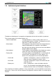
3.3 Mounting
Instead of mounting Altair directly to the instrument panel, it may be more appropriate to use a
mounting bracket so that the display is angled optimally and the buttons are within easy reach.
The device dimensions, mounting hole locations and supplied mounting brackets are illustrated in
Appendix C.
Use only the screws provided to fasten the instrument to the panel or mounting bracket. For
temporary installations, two 50mm strips of 3M Dual-Lock fasteners may be used.
Altair should be located away from the aircraft compass where possible, and the com-
pass should be adjusted after installation by a qualified aircraft maintenance engineer.
The aircraft weight and balance also may need to be recalculated by a qualified aircraft mainte-
nance engineer.
3.4 Wiring harness
The factory produced wiring harness provides a simple and safe installation of Altair. In addition,
even though the following installation examples all use the factory wiring harness, these installa-
tions are possible without the factory wiring harness.
The wiring harness provides the following connectors and terminals:
• Power supply to Altair
• Power supply from Altair to peripheral devices
• 2xRJ45 IGC connectors, for communication with peripheral devices
• OneWire bus terminals
The wiring diagram of the factory harness is documented in Appendix D. When custom harnesses
are needed, it is recommended to adapt the factory harness design.
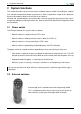
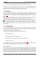
3.4.1 Terminals
The connectors X2 and X3 are special terminals of Wago Cage Clamp type that can accept bare
wires up to a cross subsectional area of 0.75 mm
2
(AWG20). To connect a wire to these terminals,
first strip 4-5 mm of the insulation. Then insert the supplied WAGO tool in the square hole next to
the desired slot to open the terminal. Insert the wire, then remove the WAGO tool. Check that no
bare wires are exposed after completion, and gently tug on the wire to ensure the clamp is secure.
Altair Owner’s Manual • ALTAIR-EN 12