Owner’s Manual Document name: Document version: Release date: ALTAIR-EN 1.2 19/02/2009 triadis engineering GmbH – Eichholzstrasse 7 – Postfach – CH-3254 Messen Phone: +41 (0)31 768 15 15 – Fax: +41 (0)31 768 15 16 – Internet: www.triadis.ch – E-Mail: admin@triadis.
Notes i Altair Owner’s Manual • ALTAIR-EN
Notes Altair Owner’s Manual • ALTAIR-EN ii
General Information Document identification / revision status This manual applies to the following Altair part numbers: • P/N T254-000-XXX (Altair Standard) • P/N T254-100-XXX (Altair Pro) triadis engineering GmbH reserves the right to update this manual as product enhancements are made throughout the life of this product. Actual version: Altair Owner’s Manual • ALTAIR-EN, Version 1.2 Version history Version 0.1 1.0 1.
Legal notices • This manual, the instrument software and firmware, and user interface design are Copyright 2006-2009 by triadis engineering GmbH . • Any decompiling, disassembly, reverse engineering, or modification of the instrument or firmware are strictly prohibited without specific written permission from triadis engineering GmbH . • Specifications may change without notice. Updates to this document will be available at http://www.triadis.
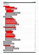
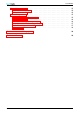
CONTENTS Contents 1 2 3 Introduction 1.1 Pilot familiarisation . . . . . . . . . . 1.2 Standard and Pro versions . . . . . . 1.3 Parts list . . . . . . . . . . . . . . . 1.3.1 Supplied parts . . . . . . . . . . 1.3.2 Accessories . . . . . . . . . . . . 1.3.3 Additional equipment not supplied 1.4 System description . . . . . . . . . . 1.5 Instrument panel interface . . . . . . . . . . . . . . . . . . . . . . . . . . . . . . . . . . . . . . . . . . . . . . . . . . . . . . . . . . . . . . . . . . .
CONTENTS D.1 Main connectors . . . . . . . . . . . . D.1.1 Power and data port . . . . . . . . D.1.2 Connector X1 . . . . . . . . . . . . D.2 Wiring harness . . . . . . . . . . . . . D.2.1 Connector X2: Power terminal . . . D.2.2 Connector X3 . . . . . . . . . . . . D.2.3 Connector X4: Primary data port . . D.2.4 Connector X5: Secondary data port D.2.5 Powersuply on X4 and X5 . . . . . D.2.6 Scheme . . . . . . . . . . . . . . . . . . . . . . . . . . . . . . . . . . . . . . . . . . . . . . . . . . . . .
1 INTRODUCTION 1 Introduction Altair is an advanced glide computer, featuring a large, bright display. The design offers unprecedented capabilities whilst having a low power consumption. The computer is a powerful Intel XScale processor, running the XCSoar glide computer and navigation system software. XCSoar is designed to integrate with intelligent variometers such as triadis engineering GmbH ’s Vega variometer and voice alerting system. Navigation is supported by having GPS input.
1 INTRODUCTION • 1 Wiring Hardness (Altair-WH-A) • 4 mounting brackets, two left-handed and two right-handed • 1 Patch cable 1m gray • 1 USB Stick drive containing documentation, maps, PC Simulator and more For a typical installation, along with the Altair unit, a wiring harness is needed. Other documents and utility programs can be downloaded from the triadis engineering GmbH website (http://www.triadis.ch). 1.3.
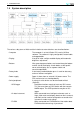
1 INTRODUCTION 1.4 System description The various subsystems of Altair and their relation to external devices are described below: • Computer • Display • Buttons • Rotary knob • Power supply • Serial peripherals - GPS/Logger - Air data instrument - FLARM 3 The computer is an Intel XScale CPU running XCSoar software. The software is highly configurable, customisable, and upgradeable. A large full color sunlight-readable display with automatic brightness adjustment.
1 - Other • Altair Recorder Unit • USB host • OneWire peripherals INTRODUCTION For example, an electronic compass, aircraft radio transceiver or mobile telephone. The PRO version contains a flight recorder unit, which can be used as a primary or backup GPS source. A slot to accept USB memory sticks allows easy transfer of flight logs, data files, and provides an easy way to perform software upgrades. A variety of devices can be connected to Altair using the Dallas Semiconductor/Maxim OneWire interface.
1 INTRODUCTION 1.5 Instrument panel interface The button and knob layout is arranged to suit operation with the left hand which is preferred. The instrument panel user interface devices are: • Power/escape button • Menu buttons • Select buttons • Rotary knob - Outer knob - Inner knob - Button press The top left button is used as a power switch and as a cancel/escape function in XCSoar. This button has an LED light which is lit when the device is on.
1 INTRODUCTION On the front of the display is a slot for USB memory sticks for file transfer.
2 SYSTEM FUNCTIONS 2 System functions This section describes how to use the various hardware features of Altair. Describing the software user interface and particular button assignments in Altair is beyond the scope of this document; these are described in detail in the XCSoar User’s Manual. All mode and selection buttons are customisable. You may change the layout of onscreen menus, assignment of buttons to hot-key functions etc. Refer to the XCSoar Advanced Configuration Guide for more details. 2.
2 2.3 SYSTEM FUNCTIONS Brightness adjustment The brightness of the LCD screen is adjustable via a backlight, and can be software controlled from the menu system in XCSoar from the menu: DISP . Brightness Adjust This allows the automatic backlight to be enabled or disabled, as well as manual adjustment and bias of the automatic backlight. When automatic backlight is enabled, the brightness field adjusts the automatic backlight system; otherwise the brightness field adjusts the backlight directly.
2 SYSTEM FUNCTIONS • Device A Device • Device A Port • Device A Speed • Device B Device • Device B Port • Device B Speed 2.5 Vega COM1 38400 Generic COM1 38400 Logger and GPS module XCSoar has a non-IGC-approved software flight recorder which can be used on Altair Standard. This is referred to as the ‘software logger’. Altair Pro has a fully IGC approved flight recorder unit, referred to here as the ‘hardware logger’.
2 SYSTEM FUNCTIONS The backup battery is designed to allow the pilot to make a final glide to a safe landing field if the main battery in the glider fails. It is not intended to be used for extended flights with all instruments on and no external power. The ‘System’ page of the ‘Status’ dialog in XCSoar shows the current external battery supply voltage. The dialog is accessed through the menu: INFO 2.8 .
3 INSTALLATION AND MAINTENANCE 3 Installation and maintenance This section describes the installation process including some of the various options, and maintenance/care of your Altair. Example installations are provided in subsection 3.7. 3.1 Installation procedure The recommended installation procedure is as follows: 1. Read all Altair manuals and the aircraft type pilot’s manual and maintenance manual thoroughly. 2. Examine the aircraft to determine its particular requirements. 3.
3 INSTALLATION AND MAINTENANCE • Ensure there is space behind the instrument for the connectors and cables. Given the fairly small size of modern glider instrument panels, finding an appropriate place for such a large screen can be difficult. Many owners will make a custom instrument panel, which can typically be done at a reasonable cost and provide the optimum layout. 3.
3 INSTALLATION AND MAINTENANCE 3.5 Power supply A voltage supply with a current limiting safety device must be secured, to cut the power in the event of an overload in the voltage supply. The safety device must be marked clearly, e.g. ALTAIR/VEGA. The best option is to use a resettable device such as a circuit breaker, however a slow-blow fuse is acceptable. Depending on the cross section, we recommend a 2.5-5A CB.
3 INSTALLATION AND MAINTENANCE Minimal installation Fully optioned installation 3.8 Initial software setup The XCSoar software needs to be configured after the physical installation of Altair, in order to properly complete the installation. This is an important process. Although Altair comes pre-configured with settings suitable for most users, there are personalisations and particulars of each installation that must be reflected in the configuration settings.
3 INSTALLATION AND MAINTENANCE • Configure the uploaded files on the site page. • Setting your home waypoint. • Configure external equipment such as the Vega variometer and FLARM. Refer to the XCSoar User’s Manual for details on how to perform the setup procedure and detailed descriptions of the various options. 3.9 Troubleshooting System diagnostic functions are built into the system.
3 Altair Owner’s Manual • ALTAIR-EN INSTALLATION AND MAINTENANCE 16
A A FEATURE SUMMARY Feature summary Notes: Feature available only in PRO version Design overview • Large, sunlight readable display with ambient light controlled backlight • Low power drain • USB host, to allow connection with USB storage drives for easy transfer of flight logs and applying software or data file updates.
A FEATURE SUMMARY Display symbols and annunciators • Wind speed and direction. • Bearing and optimal cruise track to next waypoint • Estimated glider heading adjusted for wind • Flight mode icons (circling, cruise, final glide) • GPS/FLARM status icons • Altitude required to complete task • Thermal profile display • Speed command chevrons • Compass indicator • Variometer needle with climb trend • Large selection from over 50 items of information displayed in InfoBoxes.
A FEATURE SUMMARY Task planning and management • Waypoints sorted by name or distance and direction • Full support for Assigned Area Tasks, FAI tasks and custom competition rules • Three independent Nav modes: task, landing, waypoint. Directed to one of the ten best landing options in landing mode. • Task declaration sent to external logger. • Internal, software based (non-approved) flight recorder, producing flight records in IGC format, useful as backup.
B B TECHNICAL SPECIFICATIONS Technical specifications Mechanical • Dimensions • Weight • Mount 147 x 117 x 24 mm 480g (Altair Standard), 500g + 220g (Altair PRO + Recorder Unit), Wiring harness 50g, 1m patch cable 50g, GPS antenna 70g. Instrument panel via four screws, direct to instrument panel or via mounting brackets. Computer • CPU • Memory (RAM) • Memory (Storage) • Operating system Intel XScale PXA270 at 325 MHz 64 Mb 32 Mb, approximately 8 Mb available to user Windows CE 5.
B TECHNICAL SPECIFICATIONS Environmental • Temperature range • Humidity 21 -30 to +65 °C 10-90% non-condensing Altair Owner’s Manual • ALTAIR-EN
C C PANEL MOUNT Panel mount Exterior dimensions: 147 x 117 x 24 mm. C.
C PANEL MOUNT C.
C C.
D ELECTRICAL CONNECTORS D D.1 Electrical connectors Main connectors D.1.1 Power and data port D.1.2 Connector X1 Type: 6,11: 5,7,8: 9: 2: 3: 4: 1: 12: 13: 10: 14: 15: D.2 D.2.1 Wiring harness Connector X2: Power terminal Type: 1: 25 D-Sub 15pin high density male 12V Supply in (install 2.
D 2: 3: 4: 5: 6: Note: D.2.2 Supply ground Switched 12V out to supply external devices (such as Vega or FLARM) Supply ground (used as external supply return) OneWire peripheral bus signal Supply ground (used as OneWire bus ground) Use the operating tool supplied to open the spring clamp. Connector X3 Type: 1: 2: 3: 4: 5: 6: Note: D.2.
D ELECTRICAL CONNECTORS D.2.4 Connector X5: Secondary data port Connector numbered according to IGC specifications (RX/TX normal). Description: Type: 1,2: 3: 4: 5,6: 7,8: D.2.5 Secondary data port RJ45, IGC layout GND, External device GND RS232 RX, Data received by Altair RS232 TX, Data sent from Altair Not connected 12V, External device supply, DO NOT feed in power to this Pin! Powersuply on X4 and X5 IGC specification define RJ45 Pin 7 and Pin 8 to use as power supply.
D • Keine ELECTRICAL CONNECTORS Not recommended. Reassembly the Kapton-Tabe after modifying the solder bridge! D.2.
E E MAINTENANCE AND DEBUG OPTIONS Maintenance and debug options This dialog can be opened over the Altair maintenance tool (see Altair Maintenance manual). Buttons: • Check Store Checks (and repairs if necessary) the filesystem on the data store. • Monitor COM1 Opens the COM port monitor on COM1. The monitor shows all the connected devices and their baud rate. • Monitor COM2 Opens the COM port monitor on COM2. • Monitor COM3 Opens the COM port monitor on COM3.
E MAINTENANCE AND DEBUG OPTIONS Fields: • TimeZone Time zone where the device is in use • Screen Shape Display mode: • Landscape • Portrait Altair was designed for left hand operation, triadis engineering GmbH stronly recommend to use the device in landscape orientation. • Log Device A to File All data which is sent to XCSoar by the device is written into a file by XCSoar. It is only possible to enable this function for the actual session.
F F LIMITED WARRANTY Limited Warranty triadis engineering GmbH (triadis) guarantees you as the initial buyer that the product is free from manufacturing and material defects in normal use, for a period of twelve months starting from sales date, provided that it was unused at the time of the purchase.