
Owner`s manual

Mobile Media Station
IVA-D310R etc.
or
Monitor
TME-M770/M710 etc.
Additional Source
DVD player etc.
Yellow
White
Red
Yellow
Red
White
Yellow
Red
Yellow/Blue
White/Brown
Blue
BATT
ACC
Black
White
Red
Yellow
10
11
12
13
14
15
16
8
17
8
9
1
2
3
4
5
6
7
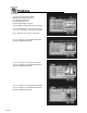
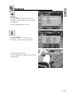
Installation and Connections
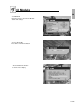
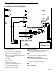
Connections and System Wiring Diagram
1
2
3
4
5
6
7
8
9
10
11
12
13
14
15
16
17
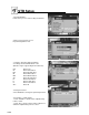
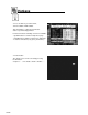
Integrated IR sensor
CI slot for Common Access Module (CAM)
RS232 connector for updating software
Mode switches for starting software download and
erasing the EEPROM
Reset button
Power status LED
2x RCA A/V auxiliary input
Antenna input socket (F-plug/female) with
integrated 5V/30mA power supply.
3x video & 1x audio RCA output
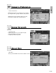
POWER
RESET
Battery lead (yellow)
Connect to a live terminal in the fuse block connecting to
the car battery (bypassing the ignition switch).
Fuse holder (3.0A)
Switched power lead (Ignition) (red)
Connect to an accessory terminal in the fuse block.
Parking brake lead (yellow/blue)
Connect to parking brake or metallic body or chassis
of the car.
Remote control input lead (white/brown)
Connect to remote control lead of monitor.
Power antenna remote output (+5V/60mA) lead (blue)
Ground lead (black)
Connect to metallic body or chassis of the car.
External IR sensor
21
-
EN