
User Guide


7
POWERGPSDISP.
EX-2EX-1
ANT.
DISPLAY OUT
NAVIGATION IN
REMOTE IN/ OUT
PRE IN/OUT
Ai-NET
FRONT
L
R
SUBW.
REAR
POWER SUPPLY
AUX OUT
AUX IN
VIDEO
AUDIO
(MONO)
R
L
RADIO ANTENNA IN
CAMERA IN
AV.SELECTOR
EXT.OUT
12345
678910
(5A)
(5A)
A
A
1
6
5
10
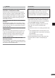
3-1.
NVE-N099P Wiring Diagram With IVA-D300R/IVA-D300RB/
TME-M770 (Touch panel-compatible Alpine products)
Power Connector
Pin Configuration
*
1
Improper connection of the
speed pulse line may cause
important safety features of the
vehicle to fail (such as the
brakes or air bags). Such
failures may result in an
accident and loss of life. We
strongly recommend that the
installation be performed by a
trained, authorized Alpine
dealer.
*
2
For further details about the
installation of the TMC antenna,
refer to “6. Installing TMC
antenna.”(page 13)
1
2
3
4
5
6
7
8
9
10
Ground (Black)
ACC (Ignition) (Red)
Mute (Pink/Skyblue)
Open
Open
Battery (Yellow)
Dimmer In (Illumination) (White/Blue)
Speed Sensor (Green/White)
Parking Brake (Yellow/Blue)
Reverse (Orange/White)
System expansion ports
13P RGB Extension Cable Included
Battery Lead (Yellow)
ACC (Ignition) (Red)
Ground (Black)
Dimmer In (Illumination) (+) (White/Blue)
Parking Brake (Yellow/Blue)
Reverse (+) (Orange/White)
Mute (Pink/Skyblue)
GPS Aerial (Included)
BATTERY
Connect to a metal
part of classis
body with screw
To the parking brake
signal line
To the vehicle speed
pulse line
Use this to connect
a device having the
IN-INT function (-)
output for Audio Mute
To the Illumination
signal line
To the Acc power lead
To reverse lights
(+12V signal)
*
1
Speed Sensor (Green/White)
Connect to VSS (Digital or Analog 0V - 3V)
TMC Antenna (Included)*
2
Attach to a bare metal chassis part of
your vehicle.