
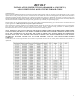
Revolv Coil Installation Instructions


3
8.
Refrigerant piping is critical on any coil installation when the
outdoor unit is to be located below the level of the coil. For
proper piping design considerations, refer to the guidelines
furnished by the manufacturer of the outdoor unit.
9. On QC coils lubricate threads and O-ring with POE oil for
proper mating. Check all field installed refrigerant connections,
both quick and sweat, with electronic leak detector, halide
torch, or soap bubbles.
10. Refer to installation instructions provided with the outdoor
unit, gas or electric furnace, and line sets for completion of
system installation.
INSTALLATION WITH ELECTRIC FURNACE:
Typical electric furnace installation consists of a coil without
cabinet installed on top of a downflow furnace or the coil inside a
cavity on either a downflow or upflow furnace.
The following Revolv installation kits are unique to manufactured
housing air conditioning and these kits are required to complete the
installation.
1. Filter (1122515) can be used on coils mounted on down flow
electric furnaces without cavities. [See #3 below for optional
filter system}
2. A Downflow Coil Support Shelf Kit with insulation
(3500.8941) for “C” & “D” Series and a Coil Support Shelf
Kit without Insulation (3500.8941B) is required to support
coils in Coleman furnaces.
3 Coil & Filter Cabinet (13010001) are recommended and many
times required for Nordyne furnaces as a preferred filter
option.
Installation procedure:
1. Turn off electrical power to the furnace by turning off
breaker in house panel. CAUTION: Furnace may be
connected to more than one supply circuit. Do not use
furnace disconnect only. Check power at furnace to
insure power is off.
2. Remove filter at top of furnace cabinet (Nordyne or Coleman
only).
3. Remove refrigerant line knockout at top of furnace (Mortex
& Nordyne only).
4. Install insulation if needed.
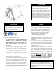
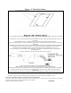
5. Attach drain pan gasket provided with coil to underside of coil
pan and center evaporator coil on furnace. See figure A on
page 5.
6. Attach filters to sides of coil.
7. Route low voltage wiring, refrigerant lines and drain tubing
through floor penetration.
WARNING: If drain hose is below 40 Deg F during
installation warm before expanding and/or forming.
8. Form 3” deep trap using (field supplied) tape
and (provided) flexible drain hose and connect to coil pan
drain securing with clamp provided. See figure B on page 5.
The most efficient use of drain material is to form a “P” trap
under the house. All pull through furnaces must have a
condensate trap in the drain line.
9. Connect refrigerant lines per instructions with line set. Make
sure to lubricate quick connect threads with refrigeration oil
for proper mating. Refer to outdoor unit installation
instructions for additional information on line set hook-ups
and proper torque values.
10. With the coil in place seal off any openings at top or bottom of
furnace to prevent air leakage or air bypass (use silver
backed tape provided, if needed).
11. Turn power on to furnace.
12. Replace front door.
INSTALLATION WITH GAS FURNACE:
Typical downflow gas furnace installation consists of a coil
without cabinet installed in the cavity of a downflow furnace. Coil
with plastic pan is not suitable for upflow oil furnaces.
Installation procedure:
1. Turn off electrical power to furnace.
2. Remove the lower front panel of the furnace, and re-route
any gas piping in front of coil compartment as required to
install coil.
3. Remove the coil cover panel(s).
4. Remove knockouts in front left bottom of furnace for routing
of refrigerant lines, low voltage wiring, and condensate
drain.
5. Attach drain pan gasket and drain elbow provided, see figure
“A” & “B”, as shown on page 5, and center coil in coil
cavity.
6. Remove knockouts from coil cover panel(s), cut fiberglass
insulation covering openings and reinstall cover.
7. Connect drain hose to condensate pan fitting, securing with
clamp. See figure “B” on page 5.
8. Install silver backed tape provided to cover openings in
interior panel door and over refrigerant lines to seal around
lines
9. Connect refrigerant lines and make sure all connections are
tight and without leaks.
10. Reconnect the gas piping if it was disconnected and seal off
any openings at bottom of furnace. National, state and local
codes must be followed.
11. Install filter if not located in furnace door.
12. Turn on gas/electrical supply and make final system check.
13.
Replace front door.
SPECIAL CONSIDERATIONS FOR SELECTING HEAT PUMP
COILS
The proper selections of indoor heat pump coils are much more
critical than selection of indoor coils for air conditioning units. The
differences are as follows:
1. Only indoor coils with expansion/check valve flow control
devices may be used with outdoor heat pump units. These
devices permit reversing refrigerant flow in the coils when
changing from cooling to heating. All Revolv expansion
valves and pistons have a built-in check making them heat
pump capable when matched with the proper AHRI rated
outdoor unit. CAP TUBE OR FIXED RESTRICTOR
COILS MUST NOT BE USED WITH HEAT PUMPS.
Do not install any coil containing refrigerant in a gas furnace
which is to be operated during the heating season without
attaching the refrigerant lines to the coil. Possible coil damage
will result from excessive pressure build up during heating
operation.
ATTENTION!
Contractor must comply with all local, state, and
federal codes and regulations when working with gas
piping. Personal injury or death may result from
improper installations!
WARNING!