
Installation Manual


8-EN
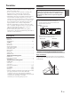
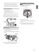
4) After adjustment, secure the display with the 2 angle
adjustment screws (M4×6) (left and right) that were removed
in Step 1 on page 6.
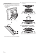
5 Attach Cover rear-L/R to the left and right sides of the
display unit.
• When removing Cover rear-L/R, push in the tab and slide it.
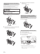
0° -20°
45°
20°
2-b
2-a
Refer to the illustration below to use the screw holes for angle
adjustment.
• Example:
To install the display at the angle of 20°, use the screw holes 2
and b.
2-c
a
b
c
2
1
Angle adjustment screws (M4×6)
(left and right)
Cover rear L
(Included)
Cover rear R (Included)
Tab