
Quick Start


ALPINE iLX-F905D 68-41657Z79-B_QRG (EN) ALPINE iLX-F905D 68-41657Z79-B_QRG (EN)
16-EN
-60 mm
Sheet Rear
(2×50 mm)
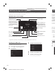
3 Attach the Cover Rear to the rear of the
display unit using 2 screws (M2.6×6).
Secure the screws, then attach the Sheet
caps.
Screws
(M2.6× 6)
(Included)
Cover Rear (Included)
Sheet caps (Included)
Install the display unit (iLX-F905D/
iLX-F115D)
1 Fix the Display unit to the slider of the main
unit using 4 screws (M5×8).
Screws (M5×8) (Included)
CAUTION
Do not adjust the display angle when the display
unit is not fixed to the slider of the main unit using
4 screws (M5 × 8). Doing so may not turn power
on.
2 Mount the Power Plate.
Power Plate (Included)
• If the Power Plate is not mounted, the display unit
may not be turned power on. Make sure to
mount it.
3 Mount the Cover Hinge using 2 screws
(M3×4).
Secure the screws, then attach the Sheet
Hinges.
Sheet Hinges
(Included)
Cover Hinge
(Included)
Screws (M3×4)
(Included)
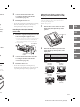
Connection Diagram of SPST Switch (sold separately)
(If the ACC power supply is not available)
Battery
FUSE (20A) (Optional)
FUSE (5A) (Optional)
SPST SW (Optional)
(Yellow)
BATTERY
(Red)
ACC
iLX-705D
iLX-F905D
iLX-F115D
i905
• If your vehicle has no ACC power supply, add an SPST (Single-Pole, Single-Throw) switch (sold separately) and fuse (sold
separately).
• The diagram and the fuse amperage shown above are in the case when the unit is used individually.
• If the switched power (ignition) lead of the unit is connected directly to the positive (+) post of the vehicle’s battery, the unit
draws some current (several hundred milliamperes) even when its switch is placed in the OFF position, and the battery
may be discharged.