
Installation guide

IPDP - installation and operating instructions
12
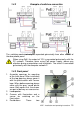
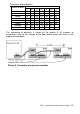
16. Switching contact 2 (NO= normally open, NC= normally closed and COM=
common output of the switch).
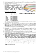
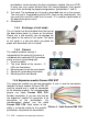
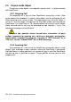
17. Connector 8 – for connecting 8
pushbuttons (integrated expansion). For
connection please use an
interconnection cable Fermax PBX
CC8. Each colour of the cable is
assigned exactly for a specific
pushbutton – see picture 3.
Connection of pushbuttons:
blue = 3rd pushbutton
brown = 4th pushbutton
yellow = 5th pushbutton
red = 6th pushbutton
white = 7th pushbutton
green = 8th pushbutton
orange = 9th pushbutton
black = 10th pushbutton
The numbers of pushbuttons begin with 3, because the first two buttons
are integrated on the basic panel.
18. Connector 5 – connection of the 8-pushbutton expansion Fermax PBX
EXP or the keypad Fermax PBX KEY. The connection is done via Fermax
PBX CC5 cable. It is a data connection only. Power supply of illumination
and the common output is on the Connector 3.
19. Connector 3 – it is used for connection of the power supply and the
common output of the pushbuttons. The original Fermax cable is used
(Fermax PBX CC3).
20. Jumper Light enables switching on/off the illumination of visit cards.
21. Switching contact of the 2nd switch (NO=normally open, NC=normally
closed and COM=common output of the switch).
22. When using Fermax IP DP, it is suggested to use either an alternating
power supply voltage min. 10VAC – max. 15VAC or a direct power supply
voltage min. 12VDC - max. - 18VDC. which is connected to the connector
"12V". The load of the power supply depends on the number of modules
used, because it is used also for powering the illumination of visit cards – if
the max. number of pushbutton panels is used, the power consumption
does not go beyond 500mA. This power supply can be also used for
powering the electrical locks, then you need to calculate alsko with the
power consumption of electrical locks. Usually it is enough to use a power
supply of 12VAC/1A÷2A.
Picture 3 Cable Fermax PBX CC8