
Installation guide
IPDP - installation and operating instructions
11
power output of the loudspeaker, you can use an add-on module with an
amplifier Fermax PBX EA.
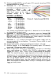
6. Loudspeaker connection SPK
7. Microphone connection MIC - attention on the right polarity!!!
8. MIC loudness setting – by the trimmer you set the desired level of loudness
of the microphone.
9. Settings of Echo cancellation. Fermax IP DP door phone panel is a hands-
free telephone. During the phone call the signal from a loudspeaker comes
back to the microphone and it comes with a delay to the calling party (that
is caused by a digital conversion and transmission of the signal). For this
reason the door phone panel is equipped by an echo cancellation circuit. It
is neccessary to pay more attention during the setting of the echo
cancellation circuit. The right setting of echo cancellation means at what
level of sound the mic turns off in Fermax IP DP in order to avoid returning
the delayed sound.
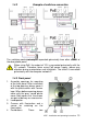
10. Setting of sensor sensitivity on surrounding light. It is valid only for
modules equipped with a camera. If case the surrounding light decreases
below at certain level (it is set by this trimmer), then the camera is
equipped by a white LED diodes for extra illumination. These LEDs are
activated during a phone call only.
11. Green LED – it signals an outgoing call (the door phone panel calls the
destination number or IP address)
12. Yellow LED – it signals an incomming call (there is a call comming to the
door phone)
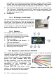
13. Ethernet connection (UTP cable) – a connection to the computer network.
If you have got a network switch with PoE or a PoE power supply (a box in
the size of a power supply adapter inserted to the input of UTP cable), then
you do not need an extra power supply for operation of the door phone
panel.
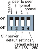
14. DIP switch – setting of default values and the mode of Fermax IP DP door
phone via a DIP switch.
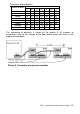
1- reserve (unused)
2- mode switching P2P / SIP server
3- basic settings – resets all values to factory settings
except for the memory of numbers
4- sets the starting IP address to 192.168.1.250
All changes show always after turning off and turning on
of the power supply (restart).
The DIP switch 3 and 4 needs to be switched back to
„on“ position after the start of VoIP module. Otherwise after the restart the
set parameters or the new IP address are rewritten back to the default
mode.
15. Output of 12VDC (max. 350mA!). This output is used primarily for
supplying the power to the lowconsumption electrical lock when PoE is
used.