ALPHATECH TECHNOLOGIES s.r.o. Jeremenkova 88, Praha 4, Czech Republic www.alphatechtechnologies.
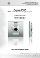
Welcome Congratulations on purchasing the door phone panel Fermax IP DP “VoIP Door Phone”, which is a SIP based VoIP version of "Fermax PBX DP" analog door phone panel. This door phone can satisfy your need of communication with visitors at the entrance to the building, to your company or at the entrance of your house. VoIP means “Voice over Internet Protocol” – the door phone is connected to the computer network and enables both P2P (peer to peer) connection – i.e.
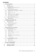
Contents 1 BASIC DESCRIPTION ...................................................................................................................... 4 FEATURES ................................................................................................................................... 4 USED TERMINOLOGY .................................................................................................................. 5 ASSEMBLY OF PANELS .................................................................
1 Basic description 1.
1.2 Used terminology Ethernet is a family of frame-based computer networking technologies for local area networks (LANs) LAN - a local area network (LAN) is a computer network covering a small physical area, like a home, office, or small groups of buildings, such as a school, or an airport 10Base-T – 10 Mbit/s, it uses 8 position modular connectors, usually called RJ45 in the context of Ethernet over twisted pair.
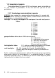
1.3 Assembly of panels The building blocks of Fermax IP DP are the basic panels which differ by its size, number of pushbuttons, if the visit card has got two or one pushbuttons. 1.3.1 Terminology and orientation in panels 4 CP 204 (item number) as a representative of terminology. It is a panel with height of 199mm. It contains an audio module, a colour camera and two times 4 pushbuttons, i.e. 8 pushbuttons in total.
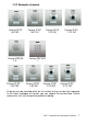
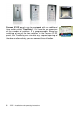
1.3.2 Examples of panels Fermax IP DP 1 AP 201 Fermax PBX EA 1A Fermax IP DP 2 AP 202 Fermax IP DP 1 AP 101 Fermax IP DP 1 CP 201 Fermax IP DP 1 CP 101 Fermax PBX KEY 1 Fermax IP DP 2 AP 201 Fermax IP DP 2 CP 202 Fermax IP DP 2 CP 102 All panels can be mounted either on the surface or they can be flush mounted. In the latest catalogue of Fermax you can choose the correct New Cityline accessories incl. for example the protective roofing.
Fermax IP DP panels can be equipped with an additional time switch called "TimeRelay". It is used for an expansion of the number of switches. It is programmable. Based on switching of one of the two switches in the Fermax IP DP panel, the TimeRelay can simulate e.g. sequent opening of the door or alternatively you can connect the exit button.
1.4 Characteristics of the modules 1.4.1 The basic module of electronics Fermax PBX DP The basic module of Fermax IP DP panel is supplied in two versions – with two pushbuttons - Fermax IP DP-2 (a version for 1 or 2 pushbuttons) and two pushbuttons with a possibility of expansion by additional 8 pushbuttons, i.e. each basic panel allows connection of up to 10 pushbuttons with no further accessories of Fermax IP DP panel.
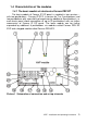
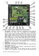
Picture 2 The real image of connection and set-up elements 1. 2. 3. 4. 5. PoE module – the Fermax IP DP panel is equipped by a circuit supplying the power over UTP cable – PoE. If your network switch is equipped by PoE, or if you have got a PoE power supply (a box in the size of a power supply adapter inserted into the input of the UTP cable), then for the correct function of the door phone panel you do not need an external power supply of 12V.
6. 7. 8. 9. 10. 11. 12. 13. 14. 15. power output of the loudspeaker, you can use an add-on module with an amplifier Fermax PBX EA. Loudspeaker connection SPK Microphone connection MIC - attention on the right polarity!!! MIC loudness setting – by the trimmer you set the desired level of loudness of the microphone. Settings of Echo cancellation. Fermax IP DP door phone panel is a handsfree telephone.
16. Switching contact 2 (NO= normally open, NC= normally closed and COM= common output of the switch). 17. Connector 8 – for connecting 8 pushbuttons (integrated expansion). For connection please use an interconnection cable Fermax PBX CC8. Each colour of the cable is assigned exactly for a specific pushbutton – see picture 3.
1.4.2 Example of switches connection The switching contact of relay is separated galvanically from other circuits of the door phone panel. When using PoE, the output of 12V is connected galvanically with the PC network. Therefore when using PoE power supply, please pay attention during manipulation and installation. The circuit is connected galvanically with the computer network!!! 1.4.3 Front panel 1. Assembly openings for mounting of the front panel.
pushbuttons can be found on the basic electronics module (the main PCB). In case you use a panel without these first two pushbuttons, then please leave them out during the programming process (pushbuttons 1 and 2). 5. Visit card. The exchange of visit card is described later on in the manual. The visit card is illuminated by white LEDs (they can be switched off). You can also find a red LED under the visit card – it is used for signallisation of the door phone panel status. 6. Microphone. 1.4.
Connection of pushbuttons: Position number on Fermax PBX EXP Colour of wire 1 2 3 4 5 6 7 Blue 11 19 27 35 43 51 59 Brown 12 20 28 36 44 52 60 Yellow 13 21 29 37 45 53 61 Red 14 22 30 38 46 54 62 White 15 23 31 39 47 55 63 Green 16 24 32 40 48 56 64 Orange 17 25 33 41 49 57 Black 18 26 34 42 50 58 The numbering of positions is shown on the picture 5. All numbers of pushbuttons refer to the settings of the door phone panel (see more in the programming section).
1.4.7 Keypad module Fermax PBX KEY The keypad module is connected via a cable Fermax PBX CC5 and a cable Fermax PBX CC3. The connection is similar to the connection of the expansion module. The difference is that the keypad module is always the last in the row (you cannot connect to the keypad module any other module). The keypad module can be only connected to the second position (i.e. directly to the basic module) or to the third position (to the output of the first Fermax PBX EXP module).
1.5 Assembly of the door phone panel 1.5.1 Surface mounting For surface mounting we offer a compact installation box. The installation box is mounted with screws with plugs to the wall. On the picture you can find an installation box, size 1. 1.5.2 Flush mounting Flush mounted installation boxes are refered to as “MKxx” or simply “flush mount installation boxes”.
2 DoorPhone VoIP Operation 2.1 Signaling Overview The all-purpose guard signals an acoustic conditions they may occur during operation. Another signaling can be done by means of red LED (placed under first label).
set point, then the DoorPhone will pick up and close the corresponding switch (if set in m=1 or m=5 modes) to the period given by seting in parameters. Then it will hang up. 2.2.2 DoorPhone with Keyboard The DoorPhone with keyboard can also include besides the keyboard up to 16 buttons of direct dialing always behaving as to be mentioned in 1.4.7(page 16) except the code lock. This one is always situated on keyboard.
2.3 Person Inside Object The person inside object is considered a person that is in phone contact with DoorPhone. 2.3.1 Outgoing Call The outgoing call is the call from DoorPhone (caused by visitor). After guard choice the telephone is ringing inside object and the pickuping up will allow speaking to the visitor at door. The code choice can close the switch, if set to m=1 or m=5 modes, change over the Day/Night modes and hang up the DoorPhone.
3 Programming of Parameters 3.1 Basic VoIP settings 3.1.1 Choosing a mode and login It is important to choose a DoorPhone mode first. The DoorPhone can work in the PeerToPeer mode or SIP server mode. The mode setting can be made by a relevant switch (DIP switch see on Pict. 9). In the SIP server mode is possible to choose SIP server (external). It can be set in a configuration interface of the DoorPhone.
In your web browser enter IP address of the DoorPhone, default is 192.168.1.250. See Pict. 2. Pict. 2 First site - video from camera Enter user name and password. User name is „admin“, default password is „1234“. See Pict. 3. Pict.
3.1.2 Language option Language setting can be made in a menu on the left panel. 3.1.3 Network settings Network settings are located in the Network seting menu item. It is possible to use DHCP service (1) or you can enter IP addresses manually. Manual configuration: After making changes click on a save and restart button. 1. Hostname – name of doorphone for resolution in nets (e.g . while using more doorphones – more entrance) 2.
3. Setting IP address, mask, eventually next network parameters, in case obscurity contact his IT manager 4. Display actual mode of IPDP – day / night 5. Return on introductory WEB site with display videos from cameras IPDP 6. short help for quick assistance in setting the parameters1 – 7. Default value – presetings to the firm settings. After making changes click on a save and restart button (display screen - see page 29). DHCP configuration: After making changes click on a save and restart button. 1.
3.1.4 Peer to peer or SIP server connection The DoorPhone can be set to the peer to peer (P2P) mode or to the SIP server mode by DIP switch (page 21). In P2P mode DoorPhone calling IP adress – in memory buttons (page 35). If you setting SIP server mode by DIP switch, so add in menu item SIP parameters After making changes use the save changes button. 1. SIP proxy server IP adress or the SIP server name and port (usually 5060 or 5061) 2. Registering data to SIP proxy server (aren't obligatory) 3.
After making changes use the save changes button. 1. There is choosing only priority using audio codecs, used codec is selection automatically at make audio connection in SIP protocol. 2. Default value – presetings to the firm settings. After making changes use the save changes button. 3.1.6 Setting video After making changes use the save changes button. 1. Resolution display video 2. Number picture per second (frequency restoring picture) 3. Setting next parameters of camera 4.
3.1.7 Viewing the video (programme PopUp) Video in doorphone IPDP is capture by USB WEB camera. Picture from camera is sending partly like series JPEG pictures to the environment WEB browser (first page on IP address IPDP doorphone) and second method is, that IPDP sending stream video in coding H.263 and in future H.264. This stream video is possible watch e.g . on telephone Grandstream series GXV3000, which has big LCD display.
3.1.8 Day intervals After making changes use the save changes button. 1. Display actual internal time (you must setting in "Service" time server) 2. Table of time interval - interval is meaning where is day, the rest is night. For example: interval 1 = 08:00-12:00, interval 2 = 14:00-17:00 - from 00:00 to 7:59 is night, from 8:00 to 12:00 is day, from 12:01 to 13:59 is night, from 14:00 to 17:00 is day and from 17:01 to 23:59 is night. 3. Default value – presetings to the firm settings.
1. Possibility switch off displaying videos on start page - safety device 2. Possibility switch off video in VoIP call (video in call makes at some systems problem) 3. Possibility change port from conventional 80 to other 4. Possibility disable / enable access over telnet 5. Default value – presetings to the firm settings. After making changes use the save changes button. 3.1.10 Service settings 1. display current version of firmware in module VoIP and in module doorphone.
basic LOG and back to, in short switch you have such LOG, which don't see writing on button. 2. Click on "Download log file" file save to you choice place. File has extension ".BIN", this is necessary rename on ".TAR". To unpacking archive "tar" use e.g . programme "PowerArchiver". File from file equip extension ".TXT". Last notice is thereon, that the text file hasn't standard ending rows. To safe display get past e.g . programme "PSPad". 3.
3.2 Setting DoorPhone parameters 3.2.1 Basic Parameters After making changes use the save changes button. 1. Mode of DoorPhone choice selects number per Day/Night DoorPhone mode or selects numbers of the first and second groups. 2. Sign for call extension * or # (10sec before call end the DoorPhone will send a notice, then the call may be extended) 3. Two commands in order to hang up the DoorPhone using both switches [2 digits].
=3 the keyboard connected on the second position (explanation of position keyboard is on chapter 1.4.7(page 16). 8. Default value – presetings to the firm settings. After making changes use the save changes button. ATTENTION! This parameters setting will sharply influence whole DoorPhone function. 3.2.2 All about relays After making changes use the save changes button. 1. Relay mode: =1 switch mode – it will close on command or password for period t1/2 (used for electrical locks, gate opening etc.
=4 bell mode – it will close after button pressing and open after period t1/2 (used for e.g. external bell or horn connections). =5 gradual opening mode – in this mode the only relay 2 will be set together with relay 1 set to mode 1. The relay 1 is activated for period t1, then the time t3 is proceeding before relay 2 closing. Then the relay 2 is activated for t2 period and afterwards the DoorPhone hangs up. Note: The only relay 1 can be activated from phone and all sequence started.
3.2.3 Time Parameters After making changes use the save changes button. 1. max. time, for which the DoorPhone is hanging up, this time can be extended during call by sign choice from telephone (* or #) – see page 31. 2. Number of incoming call rings, the DoorPhone pick up after preseted number of rings. After detection first ring – LED on front panel blinking. The number can be set from 1 to 9. 3. max.
3.2.4 Direct Dialing – Memories After making changes use the save changes button. 1. telephone number up to 16 digits, we want to store. The numbers are the numbers of the first group or numbers of Day mode. In default setting is table memoirs empty. While using setting P2P to the memoirs saves IP address e.g . 192*168*1*250, where „*“ means „.“ , while using SIP proxy server to the memoirs saves phone number e.g. 117. 2. telephone number up to 16 digits, we want to store.
4 Technical Parameters 4.1 Electrical Parameters Parameter Value Communication interface VoIP protocol supported Video Band width Power supply - adapter - or PoE Max. consumption Max. voltage of switch contact Max. current of switch contact Operational temperature Conditions Ethernet 10BaseT, 100BaseTx SIP série JPEG, stream H.263 (H.264) 300Hz – 3400 Hz 12Vss ± 2V , 12Vst ± 1V IEEE802,3af Altern. A+B 300mA 12Vss 48V at I < 1A 2A at U < 30 V - 20 to + 70°C 4.
Guarantee conditions: The product was shop-checked. The producer guarantees that this product will keep the features described in these operating instructions in the course of guarantee provided that the user will be handled with it as described in the operating manual. The guarantee will be extended by period of possible guarantee repair. When claiming in guarantee period please contact your dealer. The producer only will make the guarantee repairs.
ALPHATECH TECHNOLOGIES s.r.o. Jeremenkova 88, Praha 4, Czech Republic www.alphatechtechnologies.cz ALPHATECH TECHNOLOGIES s.r.o. Jeremenkova 88 140 00 Praha 4 Czech Republic VAT: CZ27577350 Company is registered in the Commercial Register administered by the Municipal Court in Prague, Section C, Record 116886 Banking details: Komerční banka, account No.