
Troubleshooting guide

19
745-573-B0-001 REV. A
2.0 Cabinet Installation, continued
8. Drill out the two holes in the template and insert two 5/8" X 4" (M16-2.0 x 100mm) bolts (not
supplied). The heads of the bolts will be embedded into the concrete pad when installation is
complete. Leave sufficient thread above the pad for securing the ground skirt.
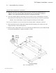
9. Center the template (with holes in position) over the form. Be sure the conduit stub-ups for the AC
input, ground rod, and AC output are positioned at the desired locations just outside the ground skirt.
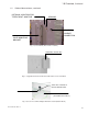
Optional: The conduit stub-ups may pass through the cement pad as shown below.
10. Pour, level, and finish concrete to the bottom of the template. Allow a curing time of 24 hours.
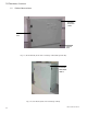
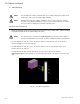
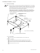
11. Attach ground skirt to power supply cabinet. Align skirt inside bottom lip of the cabinet and secure
using 10-32 X 3/8" screws from the parts kit.
12. Attach the power supply cabinet to the concrete pad using 5/8" (M16-2.0) nuts (not provided) through
the ground mounting brackets. Tighten all hardware securely.
2.2 Ground Mounting, continued
INSTALLATION PROCEDURE, CONTINUED
Fig. 2-2, Pad Dimensions