
Operator`s manual


164201257 C0
Page 31 6/13/2003
Preliminary
Lectro CPR
®
Operator’s Manual
4: Status Monitor
4.1 Installation
The communication module installs in the same basic manner for all three levels of
status monitoring. The external connections will be different as defined in Section 4.3.
4.1.1 Turn off the CPR Unit, and remove AC Power.
4.1.2 Remove the communication module cover plate (if applicable).
4.1.3 Locate and pull out the ribbon cable with the connector, inside of the CPR Com-
municator module slot.
4.1.4 Plug in the ribbon cable connector into the PC board connector on the CPR Com-
municator module.
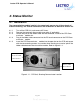
4.1.5 Insert the CPR Communicator module into the open slot on the CPR and secure
with the two mounting screws. Use caution when inserting so as not to “pinch” the
ribbon cable between the slot and the module. Refer to figure 4.1-1.
Battery LED
Reset Button
Mounting
Screws for CPR
Communicator
Figure 4.1-1: CPR Unit, Showing Communicator Location