
Operator`s manual


164201257 C0
Page 20 6/13/2003
Preliminary
Lectro CPR
®
Operator’s Manual
2.3.2 Open the cabinet. Check tightness of all battery, internal ground, and output connec-
tions. Observe condition of batteries. If the cabinet shows signs of excessive dust or mois-
ture, check for lost vent screens. Repair as required, and note any unusual conditions for fu-
ture reference.
2.3.3 Inspect the input surge suppressor (if installed) for obvious damage. If it appears intact,
check its operation with a megger or a similar device to ensure that it is functioning. Note that
a failed surge suppressor may appear visually to be OK, yet allow damaging transients and
surges to enter the power supply, and possibly the coax network. It is very important to test
the surge suppressor with a megger to make sure it is
actually protecting the power supply.
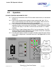
2.3.4 On the maintenance log sheet (Figure 2.3-1), mark which LEDs are illuminated on the
front panel of the CPR UPS. The presence of any red LED indicates an alarm or failure which
will require immediate attention. See Section 2.4 for troubleshooting information.
2.3.5 The CPR system will automatically and periodically load test the batteries. If a failing
battery is detected, the battery LED (red) on the front panel will illuminate. If the battery LED
is illuminated, replace the affected battery (or string of batteries) and press the “battery LED
reset” button on the front panel. See Section 3.2 for more details on how the CPR senses a
weak battery, and the proper procedures for replacement.
2.3.6 Use a true RMS meter to record AC output voltage and battery voltage at the front
panel test points. If available, use a clamp-on current probe to record AC output current at the
cable adapter.
2.3.7 Turn the battery circuit breaker off (down). Record the voltage for each battery (well
matched batteries should differ by no more than 0.2 Vdc). If the battery has a date code on
the label, record it on the maintenance log sheet.
2.3.8 Using a battery load tester, check the performance of each battery. Note that the CPR
UPS performs battery load testing automatically, so this step may be omitted if desired.
2.3.9 Close the battery circuit breaker on the front panel.
2.3.10 Force the unit into standby operation by pressing the “inverter test” button on the front
panel. Verify that the red inverter LED illuminates and that the output voltage remains within
+/- 3-5% of the nominal voltage (48, 60, 75 or 87 VAC). Verify the unit returns automatically
to normal operation after 1 to 2 minutes.
2.3.11 Confirm that only GREEN LEDs are illuminated, remove all tools and meters, and
close and lock the cabinet. This completes routine maintenance of the CPR power supply.