
Operator`s manual


164201257 C0
Page 19 6/13/2003
Preliminary
Lectro CPR
®
Operator’s Manual
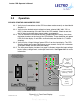
2.2.6 Check the front panel test points with a true RMS voltmeter.
CABLE AC OUT should read within 3-5% (maximum range is tap dependent) of the
configured output voltage (48, 60, 75, or 87 V). BATTERY should read between 45
and 56 Vdc, depending on the age, temperature, and state-of charge of the batteries.
2.2.7 Verify that the external LEDs on the CPR outdoor cabinet are functioning. In
normal operation, the green external LED will be ON solid, (not flashing). The
green LED flashes when the CPR system is on battery, and the red LED
flashes when there is a system alarm or failure.
2.2.8 INVERTER TEST: This test will verify proper operation of the system inverter.
Push the front panel button labeled “Inverter Test.” The red “inverter” LED
should flash on the front panel, and the fan will run. Check the CABLE AC OUT
test points for proper voltage. The inverter test lasts from 1.0 to 2.0 minutes,
and will automatically return to normal mode at the conclusion of the test. If the
inverter fails to start, check for an open battery breaker or a loose battery termi-
nal connection.
2.2.9 Once the unit has returned to normal operation, after the inverter test, the sys-
tem startup is complete.
NOTE: The CPR UPS can also be “hot started” on battery power when utility power is not
present. To hot start the CPR, close the battery breaker on the front panel, and press and
hold the “output on” button. The inverter will start within 3 seconds. The unit will operate until
the battery capacity is depleted.
CPR SHUTDOWN PROCEDURE
To shut down the CPR power supply, open the battery breaker, and unplug the AC power
cord.
WARNING: RISK OF ELECTRIC SHOCK. Hazardous electrical live parts inside the power
supply are energized from the batteries even when the input AC power is disconnected.
2.3 Maintenance
Note: It is important that secure mechanical and electrical connections be maintained on this
equipment. Secure connections will help prevent outages and equipment damage. Refer to
Figure 2.3-1 for a sample of a maintenance log sheet.
2.3.1 Inspect the external ground connections for mechanical integrity and good physical
condition. Check the cabinet for damage and check the mounting hardware for mechanical
integrity.