
Operator`s manual


164201257 C0
Page 18 6/13/2003
Preliminary
Lectro CPR
®
Operator’s Manual
2.2 Operation
CPR UPS STARTUP AND INVERTER TEST
2.2.1 Verify that all connections to the CPR have been made correctly as described in
Section 2.1.
2.2.2 Verify that the desired output voltage has been selected (48V, 60V, 75V, or
87V) via the connection at the left side of the CPR module. Check to see that
the AC input cord and Battery power cables are plugged in.
2.2.3 Turn on the external disconnect breaker (supplied by the installer), then close
the battery breaker on the front of the CPR module. There should be only green
LEDs lit on the display. If red LEDs are illuminated, see Section 2.4, Trouble-
shooting.
2.2.4 Verify that the “Output Voltage” green LED is lit on the front display. The CPR
System should now be providing power to your network. Verify with a voltmeter
at the point where the coax exits the cabinet.
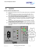
2.2.5 The front panel display includes “bar graph” indicators to describe input voltage
levels, battery voltage levels, and output load levels. See Figure 2.2-1 for more
information.
UPS
Communicating
[solid - handshake]
[flashing – data]
Weak Bat-
tery
(Red)
[solid]
UPS
Communicating
[solid - handshake]
[flashing – data]
Inverter
ON
(Red)
[flashing]
Figure 2.2-1: Front Panel Display