
Operator`s manual


164201257 C0
Page 14 6/13/2003
Preliminary
Lectro CPR
®
Operator’s Manual
2.1.3 Connect the green ground wire from the CPR UPS to the back of the mounting
bolt that holds the exterior ground clamp to the wall of the enclosure. Use the
#10 hardware provided.
2.1.4 For those power supplies with IEC power cords, plug the cord into the recepta-
cle on the left side of the power supply. Use only an HAR-approved power cord
for 50 Hz installations. Tighten the screw on the clamp until the power cord is
secure.
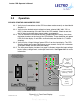
2.1.5 If the batteries are not installed, install them at this time per the instructions in
Section 3. Connect the battery sensing wire harness to the appropriate bat-
tery terminals as shown in Figure 2.1-3. Use appropriate flat washers when
connecting this harness to small battery terminals. Plug the connector from the
battery sensing harness into the mating connector on the CPR Communica-
tor Module at the front of the power supply module.
2.1.6 Locate the wire harness that connects to the LEDs on the exterior of the CPR
outdoor enclosure. Plug this harness into the mating connector on the CPR
Communicator Module at the front of the power supply module.
2.1.7 If a Tamper Switch is installed in the cabinet, plug it’s wire harness into the
mating connector on the CPR Communicator Module at the front of the power
supply module.
2.1.8 If the optional Battery Temperature Probe is used, connect the sensor plate
containing the small PC board to the most negative battery terminal (the same
terminal where the negative [black] wire from the CPR module is connected,
see Figure 2.1-3). Plug in the modular phone type connector into the RJ-11 port
on the left side of the CPR module.
2.1.9 Confirm that the battery breaker on the front of the CPR module is open. Con-
nect the ring lugs at the other end of this harness to the positive and negative
terminals of the battery as described in Section 3. Use appropriate flat washers
when connecting this harness to smaller battery terminals. Plug the large gray
battery power plug into the receptacle on the left side of the CPR module.
2.1.10 Select the appropriate output voltage for the network that this UPS is powering.
This is accomplished by plugging in the short yellow wire(s) on the left side of
the CPR module into the receptacle labeled “48 V,” “60 V,” 75 V,” or “87 V.”
This setting determines the voltage that will be present at the green and yellow
connector on the output harness (or the coaxial fitting) when the CPR unit is
operating.
CAUTION: If the unit is set for 75 or 87 VAC, make SURE that the network compo-
nents (actives and passives) are rated to handle these higher voltages before energiz-
ing the CPR power supply.
2.1.11 Confirm that the external AC disconnect is OFF.
2.1.12 Plug the AC input cord into the receptacle at the left rear of the outdoor enclo-
sure.