
Operator`s manual


164201257 C0
Page 12 6/13/2003
Preliminary
Lectro CPR
®
Operator’s Manual
1.3.3 Using the receptacle (if provided), connect the AC high input (black) to the copper
receptacle terminal, the AC neutral (white)to the silver receptacle terminal, and the
utility protective ground (green) to the green receptacle terminal. The screw tighten
torque is 20 lb-in.
1.3.4 Position all wiring neatly in the receptacle box and install the receptacle and then
the receptacle cover. NOTE: Some cabinets do not have receptacles. In this case,
the appropriate receptacle must be supplied by the installer.
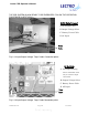
1.3.5 Using the output wire harness (green and yellow wires with “snap-in” connectors, a
seizure clamp, and O-ring) and cable “feed through” adapter from the parts kit, in-
stall the cable adapter and ground wire. Insert the cable adapter from outside the
cabinet into the paint-masked hole. The adapter may be mounted on the back of
the cabinet, (Figure 1.2-4), or in one of the holes in the bottom battery shelf (typical
for ground mounting, see Figure 1.2-5). Use the lock nut to secure the adapter and
the large O-ring to the cabinet. Tighten securely. Repeat this procedure for units
with dual outputs (24 amp model).
1.3.6 Install your choice of coax cable in the adapter. A 90° adapter may be required for
some installations. Connect the yellow output wire to the center pin of the cable by
sliding the seizure clamp into place and tightening securely. Cut the center pin of
the cable to allow about 1/4" of the pin to extend beyond the end of the clamp.
Slide the protective boot over the connector center pin and seizure clamp.
1.3.7 Connect an unbroken 6 AWG soft-drawn copper ground wire between the ground
lug provided on the back of the cabinet and the ground rod for transient voltage
protection. Note: Keep the ground wire as straight as possible. Use a ground rod
clamp of the proper type, above or below grade.
1.3.8 Proceed with the CPR Power Module installation as described in Section 2.