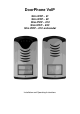
DoorPhone VoIP Slim IPDP – 01 Slim IPDP – 02 Slim IPDP – 01C Slim IPDP – 02C Slim IPDP – 01C antivandal Installation and Operating Instructions
Welcome We congratulate you on purchase of “Slim IP Door phone -VoIP” (VoIP = Voice over IP). This VoIP DoorPhone provides you by many features which allows you easy communicate with visitors of company, family houses, schools, etc.. You can easily connect it to an Ethernet network or VoIP exchange or directly to SIP server through internet conection.
Table of Contents 1 BASIC DESCRIPTION ....................................................................................... 5 1.1 FEATURES ...................................................................................................... 5 1.2 TERMINOLOGY ............................................................................................... 6 1.3 MODULE ASSEMBLY ...................................................................................... 7 1.4 MODULE FEATURES ......................
1 Basic Description 1.1 Features Two 25digit numbers (IP adresses) under each button ( includes *, #) DAY/NIGHT switching – automatically or manually Possibility to dial * or # to prolong the communication Possibility to connect 2 independent locks ( magnetic, electrical) for door opening 5 different modes of 2 integrated relays (for example: lighting, delayed opening, etc..
1.2 Terminology Ethernet is a family of frame-based computer networking technologies for local area networks (LANs). A local area network (LAN) is a computer network covering a small physical area, like a home, office, or small group of buildings, such as a school, or an airport 10BASE-T runs over four wires (two twisted pairs) on a Category 3 or Category 5 cable.
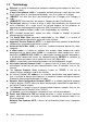
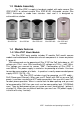
1.3 Module Assembly The Slim IPDP is supply in two basic models with color camera Slim IPDP-01/02C or without camera Slim IPDP-01/02. Antivandal version Slim IP01C Antivandal is made from stainless steel and it is designed as antivandalism solution. Slim IPDP-01 Slim IPDP-02 Slim IPDP-01C Slim IPDP-02C Slim IPDP-01C antivandal 1.4 Module Features 1.4.1 Slim IPDP Basic Module The Slim IPDP basic module includes IP module, PoE mudul, camera module and motherboard.
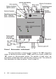
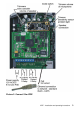
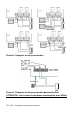
Picture 1 Basic module - motherboard The relay connection is shown on pict. 2.(page 9) The “NO” designation means an idle-disconnected contact, “COM” means a pin contact (middle) and “NC” means an idle-connected contact. The contacts of both relays are galvanically isolated each other and from other circuits as well. The variants of relay connection are shown on picture. 3 and 4.
Picture 2.
Picture 3 Examples of relays connection Picture 4 Examples of relays connection powered by PoE ATTENTION - lock is must be low power consumption, max 350mA.
Setting voice communication – trimmer position is done by manufacturer and in major installations it meets volume inquiry. Therefore changes of trimmer setting please do in necessary cases only. Basic position of trimmers, sense of rotation and meaning trimmers are illustration on picture 5. (page 11). The changes you can make up your needs. The sense Picture 5 Setting of trimmers of turning is that turning to right value is increasing.
1.5 Installation of DoorPhone VoIP Assembly 1.5.
1.5.2 Dismounting lighting of nameplate 1.5.3 Assembly Slim IPDP on the wall The installation is made by screwing to the wall by means of dowels.
1.5.4 Return lighting name plate after mounting on the wall. 1.5.5 Change of nameplates Each button has its separate nameplate hold by means of plastic flag (see figure). The paper nameplates can be printed from Excel form (to be downloaded on http://www.alphatech.cz/manualy/jmenovky1128_9.xls.
2 DoorPhone VoIP Operation 2.1 Signaling Overview The IPDP is signalling acoustically stages during its operation which can happen. Further signalling is by red LED (placed under microphone hole).
- Manual switching DAY/NIGHT is by code which is programmed in “switching codes” parametr. - mode 2 numbers groups = first press of button – always dials number saved in 1 column ( 1st group) . When you press the same button again, when busy tone is detected or when preprogrammed number of rings is over the IPDP dials number from 2 column ( 2nd group). When you press the same button again the IPDP dial number st from 1 group .
IPDP - installation and operating instructions 17
3 Programming of Parameters 3.1 Basic VoIP settings 3.1.1 Choosing a mode and login Very important is select firstly mode of IPDP in which will work inside IP network. It is P2P (peer to peer) or IPDP is registrated to SIP server. It is selected by DIP switch 2 – picture 7. The mode you cant change from WEB interface. The change of DIP switch is performed always after restart. Other switches are in position „on“ (normal). The IPDP we switch on and wait cca 1 min for unit start up.
Picture 8 First site - video from camera Enter user name and password. User name is „admin“, default password is „1234“. See picture 9.
3.1.2 Language option Language setting can be made in a menu on the left panel.
3.1.3 Network settings Network settings you find at the Network seting menu . It is possible to use DHCP service (1) or you can enter IP addresses manually. Manual configuration: After making changes click on a save and restart button. 1. Hostname – name of doorphone for resolution in nets (e.g . when you use more doorphones – more entrance) 2. Enable/disable ethernet settings via DHCP 3. Setting IP address, mask, eventually next network parameters, in case of any issue contact your IT manager 4.
DHCP configuration: After making changes click on a save and restart button. 1. Hostname – name of doorphone for resolution in nets (e.g . when you use more doorphones – more entrance) 2. Enable/disable ethernet settings via DHCP 3. DHCP client ID is name, which using for assigning two IP address to only one MAC address (in IPDP has a sense meaning as far as will be including internal SIP server) 4. Showing parameters automatically assign by DHCP - IP address and next setting 5.
3.1.4 Peer to peer or SIP server connection The IPDP can operate in peer to peer (P2P) mode or as SIP client ( SIP server registration). This mode in which you desire to operate the unit is selected by DIP switch (page 17) In P2P mode the IPDP calls IP adress – saved in memory numbers (page 37). After making changes do not forget click on „save changes“ button. 1. Selection of incoming call signalling – Ringing as default.
When you set SIP server (client) mode by DIP switch then contents of „SIP setting“ item in menu is changed. You will set different parametres than in P2P mode. After making changes do not forget click on „save changes“ button. . 1. SIP proxy server IP adress or the SIP server name and port (usually 5060 or 5061) 2. Registration data for SIP proxy server connection ( not mandatory) 3. Expiry time of registration to SIP server (interval of sending request for reregistration) 4.
3.1.5 Audio codec setting After making changes do not forget click on „save changes“ button. 1. Here you select priority of audio codec usage. Voice codec is selected automatically and in SIP protocol it is confirmed by both sides. 2. DEFAULT – factory setting.
3.1.6 Setting video After making changes do not forget click on „save changes“ button. 1. 2. 3. 1. Resolution of showing video Number picture per second (frequency restoring picture ) Setting next parameters of camera DEFAULT – factory setting. After making changes click on button „ save changes.
3.1.7 Viewing the video (programme PopUp) Video in doorphone IPDP is provided by USB WEB camera. The image from camera is sending: a) in format JPEG ( pictures) to WEB browser (first page on IP adress of IPDP), b) in format MJPEG ( motion JPEG) to POP UP software supply on CD together with unit and descripe bellow, c) in stream video format H.263 and by end of 2010 also H.264. This stream video is visible on certain types of IP phones with LCD display ( Grandstream, etc..
3.1.8 Day intervals They will be shown only when at Basic parametres is activated automatic switching DAY/NIGHT. ( since firmware release V 5.8). ( page 33.) After making changes do not forget click on „save changes“ button. 1. Showing of present time of internal clocks – clocks setting you perform in "Service - time server". 2. Intervals setting table – when is DAY – for rest of time is NIGHT.
3.1.9 User interface After making changes do not forget click on „save changes“ button. 1. Video switch ON / OFF from main page of WEB interface (mainly from security reasons, when you switch off the video then is accessable through password registration only). 2. Video switching ON/OFF during communication – some IP systems cant process SIP call includes video 3. Possibility change standard TCP port 80 to some other port 4. Possibility switch ON / OFF acces through Telnet 5. DEFAULT – factory setting.
3.1.10 Service settings 1. Showing of firmware release in VoIP modul and Door phone modul. The button „extended log“ switching way of savings SIP communication history in extended more details but shorter time period) or normal format. It isvery useful during fixing some problems.
We would like notify you that text file has not standard ending or rows CR LF but LF only. To show correctly the rows we recommend use programm "PSPad". 3. Show calls report – show call report – commands only Show report of registrationsí – here is shown registration procedure with result – succesfull / unsuccesfull 4. Show VoIP report – in new window of WEB browser is showing SIP monitor – it is log file in real time. 5. IP adress of NTP server – server for setting exact time from internet.
3.1.
3.1.12 Preparation style, language support The file of style is including 3 files which are packed (zip) to archiv „TAR“. here is example of Alphatech style. To unpack ( unzip) archiv “TAR” use programm "PowerArchiver". First file "upload_fw.sh is head of file for style which should be not changed! Second file is HTML style in syntax HTML. It is possible change font size, fonts, colors, character and lines, background color. This file you can edit up your desire.
3.2 Setting DoorPhone parameters 3.2.1 Basic Parameters After making changes do not forget click on „save changes“ button 1. Mode of numbers dial – the numbers are dialled either up DAY/NIGHT mode or from first or second group - explain on page Fel! Bokmärket är inte definierat. 2. Character to prolong the communication is either * or # (10sec before ending of communication you get notification from Door phone ( 3 beeps) about call ending. You can prolong it by pressing * or # on your phone.) 3.
3.2.2 All about relays After making changes do not forget click on „save changes“ button 1. Relay mode: =1 switch mode – it activates relay by code for certain time “time closing” (using for electrical locks, gate opening etc.) =2 camera mode – it activates relay (on) when door phone picks up and deactivate relay ( off) when door phone hang up. =3 lighting mode – – it activates relay when door phone picks up and relay stays on for certain time “time closing” even after hanging up.
delay” and after that is activated Relay 2 automatically for certain time “time closing 2”. Then Door phone hangs up. . Note: The only relay 1 can be activated from phone and all sequence started. Besides that the relay 2 can be separately activated from buttons by password. 2. Password (code) to activate relays from Door phone ( by buttons), [2 to 6 digits]. There is totally 6x codes which are control by DAY/NIGHT mode setting.
3.2.3 Time Parameters After making changes do not forget click on „save changes“ button 1. max. time of call duration. It might be prolong by dialling characters (* or #) from phone. (page 33.). 2. Number of incoming call rings before picks up. Adjustable from 1 to 9. After detection of first ring starts flashing LED on front panel. After preprogrammed number of rings the unit automatically picks up. 3. max.
3.2.4 Direct Dialing – Memories After making changes do not forget click on „save changes“ button 1. Button number (memories) – phone number up 25 digits we desire to save. Numbers saved in this column are numbers from first group, or numbers from DAY mode. When you use P2P mode then you save IP adress under button memory in format 192*168*1*231, where „*“ means „.“, . When we use mode SIP client ( SIP server) then we save under button memory phone numbers ( for example 117). 2.
4 Technical Parameters 4.1 Electrical Parameters Parameter Value Communication interface VoIP protocol supported Audio Ethernet 10BaseT, 100BaseTx SIP G.711u, G.711a, G.726-32b, GSM série JPEG, MJPG, stream H.263 (H.264 – end 2010) 300Hz – 3400 Hz 12Vss ± 2V , 12Vst ± 1V IEEE802,3af Altern. A+B 300mA 12Vss 48V at I < 1A 2A at U < 30 V - 20 to + 70°C Video Band width Power supply - adapter - or PoE Max. consumption Max. voltage of switch contact Max.
4.3 Parameters of video Video for WEB: InternetExplorer - (batch JPEG pictures - port 80) is used over and over again repeated http request ADRESA/video.jpg Mozilla, opera, Firefox … and programme PopUp (UDVguard) - (MJPEG stream - port 80) is used http request ADRESA/video.mjpg (sometimes it is necessary reload than it start up).This video is continuous and has smaller load nets. Stream video for IP phones: H.
Guarantee conditions: The product was shop-checked. The producer guarantees that this product will keep the features described in these operating instructions in the course of guarantee provided that the user will be handled with it as described in the operating manual. The guarantee will be extended by period of possible guarantee repair. When claiming in guarantee period please contact your dealer. The producer only will make the guarantee repairs.
© JR 2008-10 version V5.