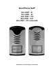
DoorPhone VoIP Slim IPDP – 01 Slim IPDP – 02 Slim IPDP – 01C Slim IPDP – 02C Slim IPDP – 01C antivandal Installation and Operating Instructions
Welcome We congratulate you on purchase of “Slim IP Door phone -VoIP” (VoIP = Voice over IP), which is the improved version of successful “New DoorPhone” (NUDV). This DoorPhone VoIP will widely manage to satisfy your needs of communication with persons at the building front door or your company entry, or family house doorway. The universality lies in possibility to connect this guard to an Ethernet network or VoIP exchange or directly to SIP server through internet conection.
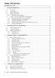
Table of Contents DOORPHONE VOIP ............................................................................................................ 1 1 BASIC DESCRIPTION................................................................................................ 5 1.1 1.2 1.3 1.4 1.4.1 1.5 1.5.1 1.5.2 1.5.3 1.5.4 1.5.5 2 FEATURES .............................................................................................................. 5 TERMINOLOGY .......................................................
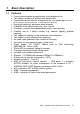
1 Basic Description 1.
1.2 6 Terminology Ethernet is a family of frame-based computer networking technologies for local area networks (LANs). A local area network (LAN) is a computer network covering a small physical area, like a home, office, or small group of buildings, such as a school, or an airport 10BASE-T runs over four wires (two twisted pairs) on a Category 3 or Category 5 cable.
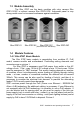
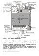
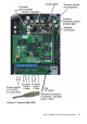
1.3 Module Assembly The Slim IPDP are the basic modules with color camera Slim IPDP-01/02C or without camera Slim IPDP-01/02. Antivandal panel is very strong metal cover for increased endurance against vandalism. Slim IPDP-01 Slim IPDP-02 Slim IPDP-01C Slim IPDP-02C (Slim IPDP-01C antivandal) 1.4 Module Features 1.4.1 Slim IPDP Basic Module The Slim IPDP basic module is assembling from modules IP, PoE mudul, camera module and motherboard. Positioning setting elements and connectors are on picture 1.
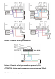
Picture 1 Basic module - motherboard The connection of relay contact terminals is shown on pict. 2. The “NO” designation means an idle-disconnected contact, “COM” means a pin contact (middle) and “NC” means an idle-connected contact. The contacts of both switches are galvanically isolated each other and from other guard circuits. The variants of connection are shown on picture. 3 and 4.
Picture 2.
Picture 3 Examples of relays connections Picture 4 Examples of relays connections powered by PoE ATTENTION - lock is must be low power consumption, max 350mA.
In newer versions available Slim IPDP function door sensor. Refer. page 34. Setting voice communication – position trimmers are presetting from manufacture and in majority case agree with, therefore changes setting altering only in necessary case. Basic position of trimmers, sense of rotation and meaning trimmers are illustration on picture 5.
DIP switch setting basic operation and default setting. See on picture 6. State of DIP switch is reading at start the IPDP, i. e. after reset. After get started system is necessary DIP switch 3 and 4 always return to the position "On", because at next reboot system would be new values overwriting by default value. Picture 6 DIP switch settings 1.5 Installation of DoorPhone VoIP Assembly 1.5.
1.5.2 Dismounting lighting of nameplate 1.5.3 Assembly Slim IPDP on the wall The installation is made by screwing to the wall by means of dowels.
1.5.4 Return lighting name plate after mounting on the wall. 1.5.5 Change of nameplates Each button has its separate nameplate hold by means of plastic flag (see figure). The paper nameplates can be printed from Excel form (to be downloaded on www.alphatech.cz/engl/basic.htm).
2 DoorPhone VoIP Operation 2.1 Signaling Overview The IPDP signals an acoustic conditions they may occur during operation. Another signaling can be done by means of red LED (placed under microphone hole). You can listen the signaling samples in Nset setting program.
- mode two number group = first press – it always dials a number set in table 1. By repeated press of the same button or detection of busy tone after dialing the DoorPhone will select the number from the second group (table 2). The next press of the same button again selects a number of the first group, etc..…… The switch (code lock) can be controlled by first 1-2 buttons of DoorPhone.
3 Programming of Parameters 3.1 Basic VoIP settings 3.1.1 Choosing a mode and login It is important to choose a DoorPhone mode first. The DoorPhone can work in the PeerToPeer mode or SIP server mode. The mode setting can be made by a relevant switch (DIP switch see on picture 7). In the SIP server mode is possible to choose SIP server (external). It can be set in a configuration interface of the DoorPhone.
In your web browser enter IP address of the DoorPhone, default is 192.168.1.250. See picture 8. Picture 8 First site - video from camera Enter user name and password. User name is „admin“, default password is „1234“. See picture 9.
3.1.2 Language option Language setting can be made in a menu on the left panel.
3.1.3 Network settings Network settings are located in the Network seting menu item. It is possible to use DHCP service (1) or you can enter IP addresses manually. Manual configuration: After making changes click on a save and restart button. 1. Hostname – name of doorphone for resolution in nets (e.g . while using more doorphones – more entrance) 2. Enable/disable ethernet settings via DHCP 3. Setting IP address, mask, eventually next network parameters, in case obscurity contact his IT manager 4.
DHCP configuration: After making changes click on a save and restart button. 1. Hostname – name of doorphone for resolution in nets (e.g . while using more doorphones – more entrance) 2. Enable/disable ethernet settings via DHCP 3. DHCP client ID is name, which using for assigning two IP address to only thing the MAC address (in IPDP porter has meaning as far as will be including internal SIP server) 4. display parameters automatically assign by DHCP - IP address and next setting 5.
3.1.4 Peer to peer or SIP server connection The DoorPhone can be set to the peer to peer (P2P) mode or to the SIP server mode by DIP switch (page 17). In P2P mode DoorPhone calling IP adress – in memory buttons (page 38). After making changes use the save changes button. 1. choice signalling of incomming call by default Ringing, possible change on Session progress - added for some SIP proxy servers that the it require 2. Symmetrical RTP - added for some SIP proxy servers that the it require 3.
If you setting SIP server mode by DIP switch, so change site of SIP parameters After making changes use the save changes button. 1. SIP proxy server IP address or SIP server name and port (usually 5060/5061) - via the server connection is made 2. SIP registrar server IP address or SIP server name and port (usually 5060/5061) - on this site registration is made, if you do not, so registration is done at the SIP proxy server 3. Registering data to SIP proxy server (aren't obligatory) 4.
3.1.5 Audio codec setting After making changes use the save changes button. 1. There is choosing only priority using audio codecs, used codec is selection automatically at make audio connection in SIP protocol. 2. Default value – presetings to the firm settings. After making changes use the save changes button.
3.1.6 Setting video After making changes use the save changes button. 1. Resolution display video 2. Number picture per second (frequency restoring picture) 3. Setting next parameters of camera 4. choice of priorities for the use of codec H.263 / H.264, if not select any codec, and sends the video call. This option is important for some VoIP systems, the presence of video call causes the inability to make calls 5. Default value – presetings to the firm settings.
3.1.7 Viewing the video (programme PopUp) Video in doorphone IPDP is capture by USB WEB camera. Picture from camera is sending partly like series JPEG pictures to the environment WEB browser (first page on IP address IPDP doorphone) and second method is, that IPDP sending stream video in coding H.263 and in future H.264. This stream video is possible watch e.g . on telephone Grandstream series GXV3000, which has big LCD display.
3.1.8 Day intervals Display only if you check automatic switch Day/Night mode on Basic parameter - page 33. Function with firmware V5.8 and higher. After making changes use the save changes button. 1. Display actual internal time (you must setting in "Service" time server) 2. Table of time interval - interval is meaning where is day, the rest is night.
3.1.9 User interface After making changes use the save changes button. 1. Possibility switch off displaying videos on start page - safety device 2. Additional security is password protection to secure access to http://ipaddress/video.jpeg (image from the camera). ATTENTION: this option has the effect that stops function the program PopUp and videos on the SNOM phone ! 3. Video surveillance (H.264) video is (so far H264) provided by the communicator (the server) protocol RTSP on port 554.
4. 5. 6. 7. In some cases also helps to add parameter about frame rate (for example for mplayer it is '-fps 5'). Full command line example for mplayer is: mplayer -fps rtsp://192.168.1.250 Push video is the choice for phones SNOM when the script was sent to the phones provide a video display on this phone Possibility change port from conventional 80 to other Possibility disable / enable access over telnet (name: root, pass: 8765) Default value – presetings to the firm settings.
1. display current version of firmware in module VoIP and in module doorphone. Button "Basic LOG" or "Extended LOG" displays to the what state LOG switch, it means you see "Extended LOG" so they switch to the basic LOG and back to, in short switch you have such LOG, which don't see writing on button. 2. Click on "Download log file" file save to you choice place. File has extension ".BIN", this is necessary rename on ".TAR". To unpacking archive "tar" use e.g . programme "PowerArchiver".
3.1.
3.1.12 Preparation style, language support File of style consist of three files packaged to the archive ".TAR".To unpacking file "tar" use e.g . programme "PowerArchiver". First file "upload_fw.sh is header file of style and this please didn't have. Second file is HTML style in syntax HTML, it is possible change font size, fonts, colours character and lines, background colour. To reliable display get past e.g . programme "PSPad".
3.2 Setting DoorPhone parameters 3.2.1 Basic Parameters After making changes use the save changes button. 1. Mode of DoorPhone choice selects number per Day/Night DoorPhone mode or selects numbers of the first and second groups. 2. Sign for call extension * or # (10sec before call end the DoorPhone will send a notice, then the call may be extended) 3. Two commands in order to hang up the DoorPhone using both switches [1 or 2 digits].
7. hasn't in this design sense, because isn't possible to connect keyboard 8. Possibility to turn off the camera for night illumination 9. Attention this option is required to detect the presence of inputs for sensors in your IPDP. Door sensors are sensors (eg magnetic contacts or part of electrical lock) to inform the opening / closing doors. Check this option to display the status of the door to the home screen video and sends this information to the program UDVguard where it is displayed. 10.
3.2.3 All about relays After making changes use the save changes button. 1. Relay mode: =1 switch mode – it will close on command or password for period t1/2 (used for electrical locks, gate opening etc.) =2 camera mode – it will close by guard pick up and open by hanging up. =3 lighting mode – it will close by guard pick up and stay closed even for period t1/2 after guard hanging up. =4 bell mode – it will close after button pressing and open after period t1/2 (used for e.g.
2. password for relay closing from buttons or keyboard [2 to 6 digits]. Total 6 passwords, they are controlled by Day/Night; the combination is entered either by DoorPhone buttons (first 1/2 buttons) or from attached keyboard (after pressing of key symbol). The relay closing influences the set switch mode and Day/Night switchover. By setting of choice mode of 2 number groups the DoorPhone is permanently in DAY mode.
3.2.4 Time Parameters After making changes use the save changes button. 1. max. time, for which the DoorPhone is hanging up, this time can be extended during call by sign choice from telephone (* or #) – see page 33. 2. Number of incoming call rings, the DoorPhone pick up after preseted number of rings. After detection first ring – LED on front panel blinking. The number can be set from 1 to 9. 3. max.
3.2.5 Direct Dialing – Memories After making changes use the save changes button. 1. telephone number up to 16 digits, we want to store. The numbers are the numbers of the first group or numbers of Day mode. In default setting is table memoirs empty. While using setting P2P to the memoirs saves IP address e.g . 192*168*1*250, where „*“ means „.“ , while using SIP proxy server to the memoirs saves phone number e.g. 117. 2. telephone number up to 16 digits, we want to store.
4 Technical Parameters 4.1 Electrical Parameters Parameter Value Communication interface VoIP protocol supported Audio Ethernet 10BaseT, 100BaseTx SIP G.711u, G.711a, G.726-32b, GSM série JPEG, MJPG, stream H.263 (CIF), H.264 300Hz – 3400 Hz 12Vss ± 2V , 12Vst ± 1V IEEE802.3af Altern. A+B 300mA 12Vss 48V at I < 1A 2A at U < 30 V - 20 to + 70°C Video Band width Power supply - adapter - or PoE Max. consumption Max. voltage of switch contact Max.
4.3 Parameters of video, access Video for WEB: InternetExplorer - (batch JPEG pictures - port 80) is used over and over again repeated http request ADRESA/video.jpg Mozilla, opera, Firefox … and programme PopUp (UDVguard) - (MJPEG stream - port 80) is used http request ADRESA/video.mjpg (sometimes it is necessary reload than it start up).This video is continuous and has smaller load nets. Stream video for IP phones: H.
Guarantee conditions: The product was shop-checked. The producer guarantees that this product will keep the features described in these operating instructions in the course of guarantee provided that the user will be handled with it as described in the operating manual. The guarantee will be extended by period of possible guarantee repair. When claiming in guarantee period please contact your dealer. The producer only will make the guarantee repairs.
© JR 2008-11 version V6.