
Manual

0700015-J0 Rev B
86
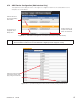
6.7.3.6 Example Three – Generator Voltage
The following is an example of a Data Log configured to monitor the input voltage of a system when a
generator is activated (for emergency backup power). In this example, the data starts logging when the
digital input signal from the generator switches on and stops once the data has collected for one hour.
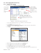
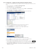
1. From the web interface, select Signals > Configure Data Logging.
2. Under Data Log Files, select an unused log file to edit.
3. Enter a filename description under File Information.
4. Enter the number of Log Records you want to keep and select FIFO as the File Save Option.
5. Under Start Trigger, select Event.
6. Click Customize.
7. In the Equation Editor, select the digital input that indicates the generator is activated.
8. Click Accept (In the Configure Data Logging window, the Digital Input # appears under Start Trigger).
9. Under Stop Trigger, select Duration and enter one hour.
10. Under Log Frequency, select Enable Time Interval. Click the Log Signals button to select the rectifier
signals for logging.
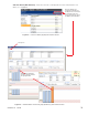
Figure 99 — Configure (Signals) Data Logging web interface window, example three
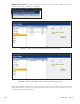
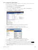
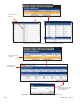
Figure 100 — Enable (Rectififer)
Signals for Data
Logging
11. Select Rectifier Signals and scroll down and check the signal
shown.
12. Select Apply (to accept changes and return to Configure Data
Logging window).
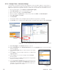
13. Click the Save icon to save the changes and click Accept
when prompted.
14. The log starts when the digital input signal from the generator
switches on and lasts one hour.
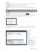
15. Select Logs & Files > Retrieve Logs. Select the file name from
the pull-down menu and then select Data Log to view the log
information in a new window. Copy and paste the data into a
spreadsheet application for analysis.