950-265-10 Rev E (02/2010)
Cordex Controller Software Version 2.0 034-136-B2 The following documents and drawings are included in this manual to provide the necessary information required for routine operation: • Program License Agreement: 048-556-10 • Operation Instructions: 034-136-C0 Alpha Technologies Ltd. Printed in Canada. © 2010 Alpha Technologies Ltd. ALPHA and CORDEX are trademarks of Alpha Technologies Ltd. All Rights Reserved.
CONTENTS 1 INTRODUCTION ............................................................................................................................................................. 4 1.1 1.2 1.3 2 QUICK START............................................................................................................................................................... 9 2.1 2.2 2.3 3 Password Security ........................................................................................................
6 MENU STRUCTURE, PROGRAMMING AND ADJUSTMENTS .............................................................................................. 32 6.1 6.2 6.3 6.4 6.5 6.6 6.7 6.8 6.9 6.10 6.11 7 ADVANCED PROGRAMMING ........................................................................................................................................ 87 7.1 7.2 7.3 8 Example: Customize .........................................................................................................................
TABLES Table A–Output channel assignments............................................................................................................................ 48 Table B–Digital input channel assignments ................................................................................................................... 50 Table C–Analog input channel assignments ..................................................................................................................
Refer to the back of this manual for Factory Service and Technical Support contact information 1 Introduction 1.1 Scope of the Manual This document describes the software features, on-site setup and operation of the Cordex System Controller (CXC) from Alpha Technologies. Refer to the Installation manual for hardware details. 1.
Visit the Alpha website at www.alpha.ca for the latest manual and product downloads 1.3 Software Overview The CXC software controls the entire DC power system. Features include temperature compensation, auto equalization, remote access, battery diagnostics, and web server and SNMP support. 1.3.1 New Features since version 1.2 The following changes/updates have been incorporated into version 1.
Refer to the back of this manual for Factory Service and Technical Support contact information 1.3.5 New Features since version 1.6 The following changes/updates have been incorporated into version 1.7 of the CXC software: 12Vdc System Support – enables the Supervisor to select the system voltage as 12, 24, 48, 125 or 220Vdc. Mixed Rectifier System – enables the use of one type of Alpha Pathfinder model rectifier working in parallel with one type of Alpha Cordex model rectifier; e.g.
Visit the Alpha website at www.alpha.ca for the latest manual and product downloads 1.3.7 New Features (since version 1.8) The following changes/updates have been incorporated into version 1.9 of the CXC software: Web Interface Facelift – provides more efficient access to software features. Speed/responsiveness has been improved over previous version (testing has shown up to four times faster).
Refer to the back of this manual for Factory Service and Technical Support contact information 1.3.11 New Features (since version 1.97) The following changes/updates have been incorporated into version 2.0 of the CXC software: Counters and Timers – counters enable the Supervisor to monitor the number of times a particular event occurs. Timers are used to measure the amount of time since an event occurred or the amount of time between two events.
Visit the Alpha website at www.alpha.ca for the latest manual and product downloads 2 Quick Start 2.1 Applying Startup Power 1. Initiate startup routine by applying power to the CXC; e.g. close battery breaker or close converter and rectifier input and output breakers. NOTE: The CXC will perform a short self-test as it boots up. Alarm alerts are normal. The LEDs perform a scrolling pattern to indicate there is activity. Please wait. 2. Check and adjust alarms and control levels in the CXC’s submenus.
Refer to the back of this manual for Factory Service and Technical Support contact information 3 Standard Features The CXC provides centralized setup, control and monitoring of a communications power system. 3.1 Password Security Two levels of password security are available: User and Supervisor. The same password cannot be used for both. User access (Section 4.7.1) enables navigation through menus, but no changes are permitted.
Visit the Alpha website at www.alpha.ca for the latest manual and product downloads 3.6 Battery Temperature Compensation The automatic battery temperature compensation (Temp Comp or TC) will function with Cordex series rectifiers that support CAN bus communications and Pathfinder series rectifiers that support RS-485 remote communications. Temp Comp may be active in either float (4.3.1) or equalize (4.3.2) mode. Temperature inputs are available on the CXC for monitoring a lead acid battery string.
Refer to the back of this manual for Factory Service and Technical Support contact information 3.7 Battery Auto Equalization Auto Equalize (Auto-EQ) is a protective feature designed to ensure optimal lead acid battery life and performance. With the CXC, auto equalize is used for two basic purposes: first, for providing a quick battery recharge after an AC power failure, and second, as a long-term battery maintenance solution. Refer to the battery manufacturer’s recommendations for equalization charging.
Visit the Alpha website at www.alpha.ca for the latest manual and product downloads 3.9 Low Voltage Disconnect Operation Whenever the system parameters require that the LVD be activated, a 60-second countdown and audible warning will commence. When the countdown reaches zero, the LVD will be activated. During this countdown, an icon on the GUI may be pressed to evoke a prompt to inhibit LVD controls – activated by entering the Supervisor password. There is a 10-minute time-out for this.
Refer to the back of this manual for Factory Service and Technical Support contact information 3.11.3 Event Log In addition, the CXC can record up to 500 events. All events are stamped with the date and time. Some of the events available include the following: All alarm events (activation and deactivation), Rectifier alarm details, Any change of state of the digital inputs, Other miscellaneous events; such as, rectifiers being turned off or on due to the Power Save feature. 3.11.
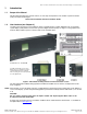
Visit the Alpha website at www.alpha.ca for the latest manual and product downloads 4 Operation 4.1 Startup and Reset Procedure When the CXC is powered-up or reset, it will first perform a 15-second self-test before displaying the Cordex logo and various identification messages. The three front-panel LED’s will illuminate temporarily, but will extinguish after the system has finished its self-test. Next, the GUI will display the power system’s parameters during Normal operating mode, see Figure 2. 4.
Refer to the back of this manual for Factory Service and Technical Support contact information 4.2.2 LCD Touch Screen Calibration A touch screen calibration page may be evoked from the user interface default operating screen: Perform a diagonal action or "swipe" from the top right area of the LCD to the bottom left area: CAUTION: Do not use a pen, pencil or other sharp object to tap on the CXC screen. This will scratch the screen and may void the warranty.
Visit the Alpha website at www.alpha.ca for the latest manual and product downloads 4.3 Mode Status (active area) and Temp Comp Indication The CXC has four modes of operation: float (FL), equalize (EQ), boost (BST) and battery test (BT). The mode, along with temperature compensation (TC or Temp Comp) activation, is indicated in the top left “active area” of the GUI, see Figure 2. The time duration, until the mode changes, will also be shown in that active area.
Refer to the back of this manual for Factory Service and Technical Support contact information 4.3.4 Battery Discharge Test or Battery Test (BT) Mode The battery discharge test is used to update the status of the lead acid battery capacity. BT can be set to run automatically or can be initiated manually (via Mode Selection button). 4.3.4.1 Definitions End/Terminal Voltage — The voltage at which the test will end or terminate.
Visit the Alpha website at www.alpha.ca for the latest manual and product downloads 4.3.4.5 BT Initiation When the test begins, an entry will be made in the event log. If enabled, an alarm will provide a warning to indicate that a Battery Test is in progress. The test will continue, depending on the type of rectifier in use, in accordance with the following algorithms (as applied to lead acid batteries): Algorithm 1 — For rectifiers that support Battery Test (BT) mode: 1.
Refer to the back of this manual for Factory Service and Technical Support contact information 4.3.4.11 Battery Discharge Test Completion The test is considered complete once the battery begins to charge. This could be due to the test ending from timeout, the system reaching the end (termination) voltage or an abort condition. Once the battery begins to charge, the recharge cycle begins. Live battery recharge information is available from the battery log web page. 4.3.4.
Visit the Alpha website at www.alpha.ca for the latest manual and product downloads 4.4 Rectifiers (and Converters) Information (active area) Tap this active area, located below Mode Status on the “home” page (Figure 2), to enter a new window of operation for converter/rectifier updates and reports, see Figure 8 below: Mode (+Temp Comp) display FL + TC 54.
Refer to the back of this manual for Factory Service and Technical Support contact information 4.5 Analog Signals Display (active area) Tap this active area3, top right of the “home” page (Figure 2), to enter a new window of operation for analog signals display and configuration, see Figure 10 below: Mode (+Temp Comp) display FL + TC 54.
Visit the Alpha website at www.alpha.ca for the latest manual and product downloads 4.6 Alarm Indication (active area) Within the default operating screen, the Alarm Indication window may show icons on the left margin to indicate various alerts (such as an active alarm and priority of the condition). In the middle of the window, text will scroll indicating alarm notification or status. Navigation keys (on the right) aid the user to view the text.
Refer to the back of this manual for Factory Service and Technical Support contact information 4.6.2 Alarm History Tap “Show Alarm History” to enter another screen that will list past alarms. Two pull-down menus enable the user to select which alarms will be displayed according to status and priority, see Figure 13 below: FL + TC 54.00V 250A Alarm will scroll here... Use pull-down menu to select status as shown Tap to “Remove Cleared” alarms from display Figure 13–Alarm History screen 4.
Visit the Alpha website at www.alpha.ca for the latest manual and product downloads Once the password is verified, appropriate access level will be granted and a pop-up window will provide acknowledgement; e.g., “Supervisor Access Granted.” If no password is entered, the user will be granted User access. In User access mode, the user cannot make changes to parameters but may navigate through menus, see Figure 23. 4.7.
Refer to the back of this manual for Factory Service and Technical Support contact information 4.8 Date and Time (active area) On the “home” page (Figure 2), below the Alarm Indication, the date and time are displayed.
Visit the Alpha website at www.alpha.ca for the latest manual and product downloads 4.10 Overview of Web Interface Refer to Chapter 9 to establish remote communications, then launch Internet Explorer 6 or greater. Under Tools\Internet Options\Security, add the logon address of the CXC to the “Trusted Sites.” Logon to address 10.10.10.201 Figure 18–Enter Network Password window Enter no USER NAME and default PASSWORD.
Refer to the back of this manual for Factory Service and Technical Support contact information 4.10.1 SNTP (Simple Network Time Protocol) This feature enables synchronization of the CXC device time with an external source; i.e., the user’s network. SNTP is an adaptation or basic subset of NTP which is used for more comprehensive device time synchronization (see www.NTP.org).
Visit the Alpha website at www.alpha.ca for the latest manual and product downloads 5 Menu Navigation and Sample Programming 5.1 Menu Navigation The sample screen shown below (Figure 23) is presented upon login, see 4.7.1. From here, the user may navigate (e.g. browse – as on a personal computer) each of the CXC’s menu items, including alarms, controls and configuration items. Mode (+Temp Comp) display FL + TC 54.
Refer to the back of this manual for Factory Service and Technical Support contact information 5.1.
Visit the Alpha website at www.alpha.ca for the latest manual and product downloads Figure 25–Menu structure Alpha Technologies Ltd. Printed in Canada. © 2010 Alpha Technologies Ltd. ALPHA and CORDEX are trademarks of Alpha Technologies Ltd. All Rights Reserved.
Refer to the back of this manual for Factory Service and Technical Support contact information 6 Menu Structure, Programming and Adjustments The CXC menu structure (Figure 25) consists of two basic components: Menu Categories and Sub-Menu Items. This chapter describes each of the CXC’s menu items, including alarms, controls and configuration items. They are arranged, as they would appear in the touch screen menus subject to product enhancements.
Visit the Alpha website at www.alpha.ca for the latest manual and product downloads 7. Figure 26–Firmware upgrade procedure NOTE: Repeat the steps above choosing Shunt MUX as required. 6.1.3 Set ADIO Module Number This menu item enables the Supervisor to select and map the order number in which CAN-enabled system devices, such as Battery Cell Monitor (BCM), are to appear in the CXC menus; shown in the examples below: Discard changes and return to previous screen Select module for mapping; e.g.
Refer to the back of this manual for Factory Service and Technical Support contact information 6.1.5 Contact Information This menu item provides for a convenient display of the site and contact information. A scroll bar enables the user to navigate the list of text items for viewing; i.e., Site Name, City, Region, Country, Contact Name, Phone Number and Site Number. 6.1.6 Temperature Units This menu item enables the Supervisor to select the temperature display units (Celsius or Fahrenheit).
Visit the Alpha website at www.alpha.ca for the latest manual and product downloads 6.1.9 System Inventory (Web Interface Only) This page enables the user to view a single list of all CAN connected devices, user inventory items, and battery information items. See Figure 31 below: Select pull-down menu for device details: Figure 31–System Inventory window (web interface only) 6.2 Converters This menu category consists of converter alarms and controls.
Refer to the back of this manual for Factory Service and Technical Support contact information 6.3 Rectifiers This menu category consists of rectifier alarms and controls. Parameters can be set/accessed such as float/equalize voltages, high/low voltage alarms, and start delay. 6.3.1 Rectifier Report This feature will enable the user to view, in a list report (see 4.4.2, Figure 9), all of the acquired rectifiers in the system. The first column lists the serial numbers of the rectifiers.
Visit the Alpha website at www.alpha.ca for the latest manual and product downloads 6.3.2.5 OVP Voltage This menu item enables the Supervisor to program one OVP setting for all connected rectifiers. OVP will disable a rectifier that outputs an abnormally high voltage. 6.3.2.6 Low Voltage Alarm (LVA) This menu item enables the Supervisor to program one LVA setting for all connected rectifiers. LVA serves as a warning to the user indicating that output voltage is dropping. 6.3.2.
Refer to the back of this manual for Factory Service and Technical Support contact information 6.3.2.15 Module Start Delay This menu item controls the stagger-start timer for all connected rectifiers. With start delay, rectifiers start up in a time-delayed sequence. This prevents excessive loading of the AC source. For example, setting a start delay time of 5 seconds will cause rectifier#1 to start at 1 second, rectifier#2 at 5 seconds, rectifier#3 at 10 seconds, etc.
Visit the Alpha website at www.alpha.ca for the latest manual and product downloads 6.3.
Refer to the back of this manual for Factory Service and Technical Support contact information 6.4.2.2 Periodic Auto-EQ Enable This menu item enables the Supervisor to control the CXC’s periodic auto equalize feature. Interval This menu item enables the Supervisor to program the time between auto equalize charging of the battery string in days. Consult the battery manufacturer for suggested equalize charge-time interval. 6.4.2.
Visit the Alpha website at www.alpha.ca for the latest manual and product downloads 6.4.3 Charge Current Control (CCC) 6.4.3.1 Enable This menu item enables the Supervisor to control the CXC’s Charge Current Control feature. Battery Properties section must be completed to enable this feature. 6.4.3.2 Charge Rate Limit This menu item enables the Supervisor to program the amount of current that goes into the battery and is dependent upon the Supervisor-entered parameter Capacity Rating (C), see 6.4.8.1.
Refer to the back of this manual for Factory Service and Technical Support contact information 6.4.4 Battery Monitor 6.4.4.1 Enable This menu item enables the Supervisor to control the CXC’s battery monitor feature. Battery Properties section must be completed to enable this feature. 6.4.4.2 Load Type This menu item enables the Supervisor to select the type of load on the system: constant power, current, or resistive. This is used for battery capacity calculations. 6.4.4.
Visit the Alpha website at www.alpha.ca for the latest manual and product downloads 6.4.5.3 Remote BT Mode This feature will force a transition to BT mode when a user-defined condition (custom alarm) is true. Enable This menu item enables the Supervisor to control the CXC’s Remote BT feature. Remote BT (Custom 1-20) This menu item enables the Supervisor to assign the Custom Alarm (see 6.5.3 Configure Alarms) number between 1 and 20. NOTE: This feature is exclusive for the Cordex series of rectifiers.
Refer to the back of this manual for Factory Service and Technical Support contact information 6.4.7 Boost (BST) Mode This feature will allow a transition to BST mode when a user-defined condition (custom alarm) is false. NOTE: Activation is manual and certain conditions must be met to prevent damage to the load. A custom alarm must be created to include all the desired factors that must be taken into account before activating BST mode. This mode will then only be permitted if the alarm is false.
Visit the Alpha website at www.alpha.ca for the latest manual and product downloads 6.4.8.4 Peukert Number This number can be entered in two ways. If the Supervisor has a Peukert number from the battery manufacturer, then it can be entered as a simple, one step numeric entry. NOTE: The Peukert number relates to the internal resistance of a battery and provides an indication (inversely) of the expected capacity; that is, a lower number is better.
Refer to the back of this manual for Factory Service and Technical Support contact information 6.5 Alarms This menu category consists of power system alarms. Parameters can be set/accessed such as power system high/low voltage alarms, AC Mains high/low voltage alarms, Supervisor programmable alarms and alarm tone enable (audible alarm buzzer). All voltage-related alarms (HVA 1 and 2, LVA 1 and 2) are based on voltage readings taken from analog input channel for the power system’s BATTERY VOLTAGE.
Visit the Alpha website at www.alpha.ca for the latest manual and product downloads 6.5.
Refer to the back of this manual for Factory Service and Technical Support contact information The web interface provides a list of all alarms in one place. The configuration of most alarms may be done on this one screen: The Alarms that have an extra (advanced) setting will appear as a link. Supervisor may toggle the check box to select e-mail notification. See 10.3.3. Click on the link to open a new window for editing the advanced setting.
Visit the Alpha website at www.alpha.ca for the latest manual and product downloads The following sections describe the menu headings and the associated lists of items. 6.5.3.2 Rectifier Alarms Rectifier Fail This menu item enables the Supervisor to set an alarm condition for a true or actual rectifier failure. The activation value is factory set. Rectifier Minor This menu item enables the Supervisor to set an alarm condition for a minor rectifier failure; i.e.
Refer to the back of this manual for Factory Service and Technical Support contact information Urgent AC Mains Fail This menu item enables the Supervisor to set a major alarm condition when the Rectifier AC Mains Fail alarm has been active for a period of time; the default activation value is ten (10) minutes: Tap on the Activation Value to edit via a virtual numeric keypad Toggle the check box to select Discard changes and return to previous screen Select from the pull-down menus: Relay Mapping – N/A or
Visit the Alpha website at www.alpha.ca for the latest manual and product downloads The following menu items enable the Supervisor to configure the alarms associated with each analog input. 6.5.3.4 Current Alarms Battery Current High This menu item enables the Supervisor to program the setting for the battery amps alarm. When the total current to the battery exceeds this setting, the alarm is activated and the message BATTERY CURRENT HIGH is displayed on the GUI.
Refer to the back of this manual for Factory Service and Technical Support contact information TC Sensor Fail This menu item enables the Supervisor to set an alarm when a sensor enabled for Temp Comp fails. 6.5.3.
Visit the Alpha website at www.alpha.ca for the latest manual and product downloads Signal and a Numeric Value Selected In this example, one signal (V1) and a numeric value (53.50) are selected for the Custom1 alarm to be triggered when [V1] > 53.50. The first operand chosen (top pull-down menu) is Analog Inputs. The next pull-down menu shows that the Supervisor must select from a list of inputs of that type. An operator is selected from the virtual keypad.
Refer to the back of this manual for Factory Service and Technical Support contact information Example 1: Add More Rectifiers Alarm The function of the following equation is to activate a custom alarm when load increases to a point where redundancy is compromised, but before any rectifiers go into power limit. Enter the equation taking into consideration logic operators and the number and type of brackets used: [Load Current] > ((([# Acquired Rectifiers]-1)*55)-5.
Visit the Alpha website at www.alpha.ca for the latest manual and product downloads Scheduler Usage The controller has basic scheduling capability that is implemented by using a System Time or System Date signal in any customizable equation; used to trigger external events on a timely basis, whether daily or at a specific date. This is accomplished by using the System Time or System Date signal as an operator in a Custom Alarm equation, which has been configured to change the state of a relay output.
Refer to the back of this manual for Factory Service and Technical Support contact information The following sub-section describes the converter alarms menu headings and the associated items. 6.5.3.11 Converter Alarms Converter Fail This menu item enables the Supervisor to set an alarm condition for a true or actual converter failure. The activation value is factory set. Converter Minor This menu item enables the Supervisor to set an alarm condition for a minor converter failure; i.e.
Visit the Alpha website at www.alpha.ca for the latest manual and product downloads 6.5.4 ADIO Alarms Detail 6.5.4.1 View Details This menu item enables the user to select an ADIO device (i.e., Cordex Smart Peripheral) that is connected to the CXC and view the alarms with respect to: Cell Deviation, Current, Voltage, Temperature, and Comms. 6.5.5 Alarm Hysteresis 6.5.5.1 Voltage Voltage Hysteresis applies only to Voltage Alarms (6.5.3.5).
Refer to the back of this manual for Factory Service and Technical Support contact information 6.5.7 Configure ALCO This feature is found under the Global Alarm Configuration menu (submenu of Alarms), see Figure below: Discard changes and return to previous screen Toggle the check box to select Sliders and scroll bars are used for navigation Select menu item to configure Accept changes and return to previous screen Figure 45–Configure ALCO window 6.6 6.5.7.
Visit the Alpha website at www.alpha.ca for the latest manual and product downloads 6.6.1 Calibrate Analog Inputs This menu item provides a direct link to the Analog Inputs menu heading; which may also be accessed via the menu item Configure Signals, see 6.6.2. 6.6.1.1 Analog Inputs This menu item will display a list of all the existing analog input channels.
Refer to the back of this manual for Factory Service and Technical Support contact information Calibration From this pop-up window, the Supervisor can calibrate the selected channel by setting the high point or low point or both as shown in the following example: Figure 46–Analog Inputs calibration example Tap to Cancel or proceed through the screens in the example above. Apply or Discard the calibration information as desired.
Visit the Alpha website at www.alpha.ca for the latest manual and product downloads Static Calibration Static calibration enables the Supervisor to calibrate controller analog inputs without the need for a live signal at the input. This is especially useful for calibrating current inputs for systems in the field.
Refer to the back of this manual for Factory Service and Technical Support contact information 6.6.2 Configure Signals This menu item provides a link for the Supervisor to configure controller Signals (and Analog Inputs described above). The status of Digital Inputs and Rectifier Signals may also be viewed under this menu. 6.6.2.1 Controller Signals Select this heading from the pull-down menu to access/edit the list of Controller Signals (4.
Visit the Alpha website at www.alpha.ca for the latest manual and product downloads AC Mains Voltage Correction – provides the means to apply a correction factor to the reading coming from the rectifier. There are correction factors for each ac input phase and for the combined average ac voltage. Figure 49–AC mains voltage correction (via web interface) 6.6.2.5 Custom Signals Select this heading from the pull-down menu to access/edit a list of Custom Signals.
Refer to the back of this manual for Factory Service and Technical Support contact information Example Three – Configure (Battery Temperature sensors) From this window, the Supervisor can configure the Battery Temperature signal and sensors. Use the pull-down menu to set the decimal precision and tap/toggle the check boxes to enable sensor(s) for battery temperature as shown in the following example: Check boxes are disabled if the input is not a temperature input. User cannot enable.
Visit the Alpha website at www.alpha.ca for the latest manual and product downloads For the Custom Alarm equation, the Custom Signal is compared to the maximum* allowable voltage deviation in battery string halves. In this example a message is recorded when the midpoint voltage is in error. * Some fine-tuning may be required to obtain the ideal setting that is sensitive enough to detect a ‘bad’ cell and will not produce false alarms.
Refer to the back of this manual for Factory Service and Technical Support contact information 6.6.2.9 Counter Select this heading from the pull-down menu to access individual counters.
Visit the Alpha website at www.alpha.ca for the latest manual and product downloads 6.6.2.11 ADIO Signals Select this heading from the pull-down menu to access individual signals for an ADIO (Analog Digital Input Output) Device; i.e., Cordex Smart Peripherals (ref. 4.5.7).
Refer to the back of this manual for Factory Service and Technical Support contact information View Live Status (Web Interface) – ADIO live information is displayed via another link/window for the device, if so equipped: When the BCMC (if so equipped) is selected from the Signal List, a new button/link provides access to a more comprehensive view of the BCMC parameter/status.
Visit the Alpha website at www.alpha.ca for the latest manual and product downloads ADIO Configure Signals – enables the Supervisor to input a value for a range to be applied to all selected channels.
Refer to the back of this manual for Factory Service and Technical Support contact information 6.6.3 Data Logging (Web Interface Only) 6.6.3.1 Configure Data Logging To edit the data log configuration, browse to SIGNALS page and select Configure Data Logging: Start/Stop trigger buttons are found at the top of this window. Delete will remove the file altogether. Description of log file is shown here.
Visit the Alpha website at www.alpha.ca for the latest manual and product downloads Log Frequency – determines how often the data is collected. The default time interval is 60 seconds and the range is from ten to 86,400 seconds (24 hours). An interval may also be set based upon when a selected signal changes by the Delta Level; click on the value to edit.
Refer to the back of this manual for Factory Service and Technical Support contact information 6.6.3.3 Retrieve Logs From the LOGS & FILES page of the web interface, select Retrieve Logs: Figure 67–Retrieve Logs web interface window On the new page, locate the Data Log drop-down menu and “Select a data log file” to view the log information: Figure 68–Sample (data) log information web interface window NOTE: The date and time is recorded for every data sample.
Visit the Alpha website at www.alpha.ca for the latest manual and product downloads 6.6.3.4 Example One – Logging Three Phase Voltage Input (Rectifier System) The following is an example of a Data Log configured to monitor the voltage input for a three phase rectifier system.
Refer to the back of this manual for Factory Service and Technical Support contact information 6.6.3.5 Example Two – Battery System The following is an example of a Data Log configured to monitor the battery voltage, current, temperature and other parameters for a battery system.
Visit the Alpha website at www.alpha.ca for the latest manual and product downloads 6.6.3.6 Example Three – Generator Voltage The following is an example of a Data Log configured to monitor the input voltage of a system when a generator is activated (for emergency backup power).
Refer to the back of this manual for Factory Service and Technical Support contact information 6.6.4 ADIO Device Configuration (Web Interface Only) The Supervisor may modify the name of the signal or configure an alarm for the selected item. Some examples are shown below. Select the device before accessing Modify Name button Once the device is highlighted, select Modify Name Configure Alarms is not an option for the 4R/8D device. See note below.
Visit the Alpha website at www.alpha.ca for the latest manual and product downloads Select the device to configure Figure 78–ADIO device configuration examples (showing BCM device) Select the device to configure Select the string to be configured Select apply changes once ADIO configuration has been completed Figure 79–ADIO device configuration examples (showing BCMC device) Alpha Technologies Ltd. Printed in Canada. © 2010 Alpha Technologies Ltd.
Refer to the back of this manual for Factory Service and Technical Support contact information 6.7 Controls This menu category consists of power system controls. Parameters can be set/accessed such as low voltage disconnect (LVD), high voltage shutdown (HVSD), and counter electro-motive force (CEMF) in/out. Many of the parameters are similar to the items found in 6.5.3 Configure Alarms; such as, relay mapping and alarm priority.
Visit the Alpha website at www.alpha.ca for the latest manual and product downloads 6.7.1.1 DOD Activation This menu item (LVD DOD Control) allows the Supervisor to configure each LVD control for activation once the percentage of Depth of Discharge (DOD) has increased above a threshold. This control works in conjunction with the existing LVD countdown timer and the disconnect voltage. Whichever programmable parameter is met first, the LVD will be activated.
Refer to the back of this manual for Factory Service and Technical Support contact information 6.8 Communications This menu category consists of rectifier and power system communications controls. Parameters can be set/accessed such as the web interface (e.g. IP address), and baud rates. For a more detailed explanation, refer to the next chapters of the CXC Communications Menu Parameters and Remote Communications. 6.8.
Visit the Alpha website at www.alpha.ca for the latest manual and product downloads 6.8.3.1 CXCI IP Address Reset and Startup This feature enables the user to reset the IP address of the CXCI. It is a function of the front panel reset button on Cordex controllers that have only a 4-digit display. The reset button located on the front panel of the CXCI is for restarting the microprocessor. When pressed momentarily, the unit beeps twice then resets.
Refer to the back of this manual for Factory Service and Technical Support contact information 6.8.5 Craft Port (“PPP Connection Device/Front Craft Port” per web interface) This menu item enables the Supervisor to set the baud rate at which the Craft Port communicates with the CXC. Select from the pull-down menu. 6.8.
Visit the Alpha website at www.alpha.ca for the latest manual and product downloads 6.9 Hardware This menu category consists of output relay configuration and testing. See also 6.5.3.1 for Overview. 6.9.1 Configure Relays This menu item will display a list of the normal state of all the existing output relays. A relay must be selected in order to configure the settings. See Figure 86 below.
Refer to the back of this manual for Factory Service and Technical Support contact information 6.10 Logs & Files (Web Interface only) This menu category consists of retrieving logs for event, battery, statistics and data; and managing files for configuration, dynamic (editable) text, and language. 6.10.1 Retrieve Logs See also 6.6.3.3 (under Data Logging). Figure 88–Retrieve Logs web interface window 6.10.
Visit the Alpha website at www.alpha.ca for the latest manual and product downloads 6.10.2.1 Printing Custom Site Configuration Right-click in the window showing the settings and be careful to then select Print Preview. See Figure 90 below: Figure 90–Logs & Files “Print Preview” (web interface) CAUTION By default the browser will print out all settings requiring approximately 50 letter-size pages. Continue with the page setup and print dialog as required.
Refer to the back of this manual for Factory Service and Technical Support contact information 6.10.4 Manage Language Files Language files can be uploaded via web interface. The CXC can be set up for a maximum of three language files (default plus two others) at one time pending availability. Figure 92–Manage Language Files web interface window 6.11 Supervisor This menu category displays only when logged in with Supervisor level access.
Visit the Alpha website at www.alpha.ca for the latest manual and product downloads 7 Advanced Programming 7.1 Example: Customize When configuring Alarms (Section 6.5.3), Signals (6.6.2), or Controls (6.7), an option to CUSTOMIZE will be presented at the bottom of the screen, see Figure 95 below. This enables the Supervisor to program separate triggering equations into the CXC software.
Refer to the back of this manual for Factory Service and Technical Support contact information Mathematical operators: + = Add - = Subtract * = Multiply / = Divide Keypad changed from numeric to symbol Select Sym for mathematical and logic operators [select 123 to return to numeric keypad] Figure 98–Equation builder keypad symbol key Logical operators: & = AND | = OR ! = NOT TRUE = is EQUAL THAN (compare for equality) > is GREATER THAN < is LESS THAN ( is OPEN PARENTHESIS (used with a close parenthesis
Visit the Alpha website at www.alpha.ca for the latest manual and product downloads 8 CXC Communications Menu Parameters This chapter provides definitions regarding Ethernet, IP Addresses, and CXC communications (port) configurations. 8.1 Ethernet Port Configuration 8.1.1 About IP Addresses IP stands for Internet Protocol.
Refer to the back of this manual for Factory Service and Technical Support contact information 8.1.2 IP Information This is where the CXC’s current IP Address Settings are displayed for the LCD menu. Scroll bars enable the user to navigate the list of text items for viewing; i.e., IP Address, Subnet Mask, Gateway, and Ethernet/MAC Address. For the web interface, the current IP Address Settings are found by clicking on the “View Live Status” link of the Communications submenu. 8.1.
Visit the Alpha website at www.alpha.ca for the latest manual and product downloads 8.2.2 Rear Modem Port Rear Modem Port provides three choices for installed modem; selected from a pull-down menu: Internal Modem, External Modem, and NULL Modem. When connection is established, the HTTP web server, SMTP outbound e-mail notification and/or SNMP dial out trap notification can be delivered through PPP. Modem Init String needs to be specified in order to initiate external (remote) modem connection.
Refer to the back of this manual for Factory Service and Technical Support contact information 8.3.3 Null Modem Direct Cable Connection Support The CXC supports the use of a direct DB-9 null modem cable connection to a computer running Windows 2000. The null modem cable is connected to either the front panel RS-232 serial craft port interface or rear RS-232 serial port interface (requires the CXC to be supplied with the List Option 95 Communications Board assembly).
Visit the Alpha website at www.alpha.ca for the latest manual and product downloads 9 Remote Communications The instructions provided in this chapter should enable the user to establish remote communications with the CXC. The communications protocol supports a web interface. All CXC models may be set up, monitored and tested with an Ethernet 10/100 Base-T either locally or remotely. Local connection is also possible with a PPP serial data connection.
Refer to the back of this manual for Factory Service and Technical Support contact information 9.2 PPP Serial Data Connection The user must set up a “direct cable connection” for the workstation to be connected (with a null modem cable) to the CXC Craft port (address 10.10.10.203). Follow the example (e.g., in Windows 2000) below: 9.2.
Visit the Alpha website at www.alpha.ca for the latest manual and product downloads 9.2.2 Network Connection Wizard This wizard is used to create several different types of connection, so it is important to follow the steps carefully. The first page is merely a welcome screen. Select NEXT to continue. On the page shown below, select CONNECT DIRECTLY TO ANOTHER COMPUTER and then select NEXT to continue. Figure 104–Network Connection Type Host or Guest? Page Select GUEST, and then select NEXT to continue.
Refer to the back of this manual for Factory Service and Technical Support contact information 9.2.3 Direct Connection Properties Right-click on the DIRECT CONNECTION icon to verify the properties of the new connection as follows: Figure 106–Direct Connection Properties General Tab Select a device COMMUNICATIONS CABLE BETWEEN TWO COMPUTERS… as shown above. Options Tab Uncheck PROMPT FOR NAME… Security Tab Check TYPICAL (RECOMMENDED SETTINGS) and select ALLOW UNSECURED PASSWORD.
Visit the Alpha website at www.alpha.ca for the latest manual and product downloads 9.2.4 Phone and Modem Options Select START MENU, SETTINGS, and then select CONTROL PANEL. Open PHONE AND MODEM OPTIONS to check the speed of the COM port as shown below: Figure 108–Phone and Modem Options Select PROPERTIES and verify Maximum Port Speed (determined previously) as shown below: Figure 109–Modem Properties Select OK to close each of these windows. Alpha Technologies Ltd. Printed in Canada.
Refer to the back of this manual for Factory Service and Technical Support contact information 9.2.5 Connect Direct Connection Select START MENU, SETTINGS, and then select NETWORK AND DIAL-UP CONNECTIONS as before. Select DIRECT CONNECTION to open password entry window shown below: Figure 110–Connect Direct Connection (password entry) Select CONNECT to continue. A Connection Complete dialog box should be presented as below: Figure 111–Connection Complete (message) Select OK to continue.
Visit the Alpha website at www.alpha.ca for the latest manual and product downloads 9.2.6 Dial the Modem and Connect to the CXC 1. 2. 3. 4. 5. 6. Once the connection is established (icon in bottom right tray), right click on the icon Select Status Click on the Details tab Use the Server IP address for the web address The Server IP address default is ’10.10.10.203’ (as shown below) Access the CXC via Internet Explorer 6 or up. Figure 112–Modem Status Alpha Technologies Ltd. Printed in Canada.
Refer to the back of this manual for Factory Service and Technical Support contact information 9.3 Modem Connection 9.3.1 Controller Setup NOTE: If using a CXCI: configure modem settings via Ethernet (web server) only. CAUTION Do not connect anything other than the Alpha modem and Alpha-supplied DB-9 cable to the D-sub port on the front of the CXCI. NOTE: To set the modem number of rings, edit the MODEM INIT STRING; for example: E1MIQ0X4S0=N, where N is the number of rings.
Visit the Alpha website at www.alpha.ca for the latest manual and product downloads 9.3.2 Computer Setup 1. In Windows® 2000, select START menu, SETTINGS, and then select NETWORK AND DIAL-UP CONNECTIONS. 2. Double-click the MAKE NEW CONNECTION icon to start the Network Connection Wizard. 3. Select DIAL-UP TO PRIVATE NETWORK. Note: Some systems may come up with another pop-up selection for modem or infrared port. Modem should be selected. 4.
Refer to the back of this manual for Factory Service and Technical Support contact information 10 Simple Network Management Protocol (SNMP) 10.1 Overview SNMP was developed in 1988 as an operating system for the management of the data flow from a series of remote information generators, or Agents, connected to a central computer, or Manager, by way of a network.
Visit the Alpha website at www.alpha.ca for the latest manual and product downloads 10.1.3 Typical UDP Transport Agent listens on UDP port 161. Responses are sent back to the originating NMS port from a dynamic port, although many agents use port 161 also for this target. Maximum SNMP message size is limited by maximum UDP message size; i.e. 65507 octets. All SNMP implementations have to receive packets at least 484 octets in length.
Refer to the back of this manual for Factory Service and Technical Support contact information 10.1.4 Variable Binding (VarBind) A VarBind is a sequence of two specific fields, an Object Identifier (ID) and the value for/from that Object ID. A VarBindList is a simple list of these pairings. Among the Event Properties employed, the following example highlights two new VarBinds for version 2 software: Timestamp & Alarm Trigger.
Visit the Alpha website at www.alpha.ca for the latest manual and product downloads 10.3 Communication Configuration SNMP Communication Configuration is only accessible via the web interface. Select Configure SNMP from CXC web interface Communications menu as shown below. 10.3.1 SNMP Multiple Community Names This menu item enables the User to configure multiple CXC SNMP community settings for get (read) and set (write).
Refer to the back of this manual for Factory Service and Technical Support contact information 10.3.3 Event Notification Destination – Multiple SNMP and SMTP Destinations This menu item enables the Supervisor to add up to eight (8) separate destinations for SNMP and SMTP dial-out of e-mail notifications. A wizard is provided to assist the Supervisor with the addition of new destinations. See the following example. NOTE: Login credential information must be provided by your network administrator.
Visit the Alpha website at www.alpha.ca for the latest manual and product downloads For SNMP Configuration, Dedicated Connection is the default selection of Connection Type: -Information for Destination was established in the configuration window. For Email Configuration: -Enter SMTP IP Address unless already established in the configuration window. -Select Host Name if CXC has a fully qualified domain name that can be resolved by a DNS server. IP address must be obtained automatically from DHCP server.
Refer to the back of this manual for Factory Service and Technical Support contact information 10.3.3.1 Master SNMP Destination This menu item enables the Supervisor to set a NMS destination as master. Select from the pull-down menu. Select None if SNMP connection is by dial-out or no trap recovery (after network block out) is required. This is the default to be backward compatible with legacy CXC trap notification method. 10.3.3.
Visit the Alpha website at www.alpha.ca for the latest manual and product downloads 11 Factory Ranges and Defaults Submenu Item Programmable Range Default Setting 12Vdc 24Vdc 48Vdc 125Vdc 220Vdc Float (FL) Voltage 0-9999999999 13.50V 27.00V 54.00V 130.50V 229.5V Equalize (EQ) Voltage 0-9999999999 13.75V 27.50V 55.00V 132.92V 233.75V Battery Test (BT) Voltage 0-9999999999 11.50V 22.00V 44.00V 106.33V 187.00V OVP 0-9999999999 14.25V 29.00V 57.00V 137.75V 242.
Refer to the back of this manual for Factory Service and Technical Support contact information Submenu Item Programmable Range Default Setting 12Vdc 24Vdc 48Vdc 125Vdc 220Vdc 25.68V 0.0 AH 100% 51.36V 124.12V 218.28V 178.
Visit the Alpha website at www.alpha.ca for the latest manual and product downloads Submenu Item Programmable Range Default Setting: Priority, Activation Value 12Vdc Rectifier Fail Rectifier Minor Rect. Major Fail Count Rect. Minor Fail Count Rectifier Lockout Out of Tolerance Rect. Communications Lost Rect. Equalize Activated Rect. AC Mains Fail Max.
Refer to the back of this manual for Factory Service and Technical Support contact information Submenu Item LVD 1 LVC 1 Alarm Priority Relay Mapping Control Alarm cutoff LVD 2 LVC 2 Alarm Priority Relay Mapping Control Alarm cutoff LVD 3 LVC 3 Alarm Priority Relay Mapping Control Alarm cutoff LVD 4-10 LVC 4-10 Alarm Priority Relay Mapping Control Alarm cutoff LVD Inhibit (Status) Alarm Priority Relay Mapping Alarm cutoff High Volt.
Visit the Alpha website at www.alpha.ca for the latest manual and product downloads Submenu Item Programmable Range IP Address Subnet Mask Gateway Modem Rear Port Device Baud Rate Enable Callback Modem Init String Craft Port Baud Rate RAS Client Settings Phone Number Login Account Domain Name Password Web Settings Routing SMTP Server Settings IP Address Send Domain From Address To Address Copy Address Check = obtain automatically 0.0.0.0 – 255.255.255.255 0.0.0.0 – 255.255.255.
Refer to the back of this manual for Factory Service and Technical Support contact information 12 Modbus® Communications Protocol This feature enables CXC communication of alarms and live signals using Modbus protocol (messaging structure developed by Modicon®. A message is encoded in Remote Terminal Unit (RTU) data format and is communicated upon query via Transmission Control Protocol (TCP) to any Modbus supervisor or master. Reference: Modbus application protocol specification v1.1a (www.Modbus-IDA.
Visit the Alpha website at www.alpha.ca for the latest manual and product downloads -- -- -- 0x0041 Alarm1_In_Alarm_Table_2_Status_Bit Distribution Fuse BINARY 0x0042 Alarm2_In_Alarm_Table_2_Status_Bit Battery Fuse BINARY 0x0043 Alarm3_In_Alarm_Table_2_Status_Bit LVD Manual In BINARY 0x0044 Alarm4_In_Alarm_Table_2_Status_Bit LVD Manual Out BINARY 0x0045 Alarm5_In_Alarm_Table_2_Status_Bit Converter Fail BINARY 0x0046 Alarm6_In_Alarm_Table_2_Status_Bit Conv.
Refer to the back of this manual for Factory Service and Technical Support contact information 0x0191 Alarm17_In_Alarm_Table_7_Status_Bit Custom 17 BINARY 0x0192 Alarm18_In_Alarm_Table_7_Status_Bit Custom 18 BINARY 0x0193 Alarm19_In_Alarm_Table_7_Status_Bit Custom 19 BINARY 0x0194 Alarm20_In_Alarm_Table_7_Status_Bit Custom 20 BINARY -- -- 0x01C1 Alarm1_In_Alarm_Table_8_Status_Bit Real Time Clock Error BINARY 0x01C2 Alarm2_In_Alarm_Table_8_Status_Bit Invalid Device Firmware BINARY
Visit the Alpha website at www.alpha.
Refer to the back of this manual for Factory Service and Technical Support contact information 0x0290 Alarm80_In_ Alarm _Table_10_Status_Bit ADIO_16_Comms Alarm -- -- -- 0x0040 *(X-1) Alarm1_In_Alarm_Table_X_Status_Bit Read alarm1 status bit in alarm table X -- -- -- AX AlarmAX_In_Alarm_Table_X_Status_Bit Read alarmAX status bit in alarm table X BINARY BINARY BINARY Table O–CXC Modbus PDU address definition for function code 0x02 (read discrete inputs) Number of Bytes PDU Address Variable
Visit the Alpha website at www.alpha.
Refer to the back of this manual for Factory Service and Technical Support contact information 13 Trouble-shooting To use the following trouble-shooting guide, look for the specific symptom that you are experiencing: Symptom Solution Rectifier Communications Lost (RECT COMMS LOST) Check RS-485 or CAN cable connections for breaks and loose contacts. Ensure all rectifiers are secured and tightly screwed in to the shelf. Perform “Inventory Update” (from RECTIFIERS menu).
Visit the Alpha website at www.alpha.ca for the latest manual and product downloads 14 Alpha Conventions 14.1 Numbering System Alpha Technologies uses an eight-digit drawing number system, which is broken into three blocks. The first three digits describe the category of the product; e.g. rectifier or fuse panel. The next three digits indicate the sequence in which the product number was allocated in a particular category.
Refer to the back of this manual for Factory Service and Technical Support contact information Index A alarms, 21, 35, 36, 45, 46, 47, 49, 50, 51, 52, 56, 57, 62, 63, 111, 120 alerts, 23, 25, See alarms analog signals, 12, 18, 22, 23 auto equalize, 9, 12, 39, 40 Auto-EQ. See auto equalize B battery monitor, 12, 42 test, 18, 19 baud, 9, 80, 81, 82, 96, 113 BCT equalize, 43, 44 breakpoints, 11, 39 BT. See battery test, See mode (of operation) C CAN bus. See communications Celcius.
Service Centers Factory Service Centers USA Alpha Technologies Services Inc. ATTN: RMA Returns 3116 Mercer Avenue Bellingham, WA, 98225 USA Tel: +1-360 756 4904 Fax: +1-360 647 0498 Email: returns-usa@alpha.ca Asia-Pacific PCM Electronics (Dong Guan) Co., Ltd.
www.alpha.