AlphaNet™ Series External DOCSIS® Transponder Technical Manual Model XP-EDH-A2 Model XP-EDHEffective: October 2009 Alpha Technologies
Power Alpha Technologies ®
AlphaNet™ Series External DOCSIS Transponder Model XP-EDH-A2 Technical Manual 745-838-B2-001, Rev. A Effective Date: October 2009 Copyright © 2009 Alpha Technologies, Inc. member of The GroupTM NOTE: Alpha denies responsibility for any damage or injury involving its enclosures, power supplies, generators, batteries or other hardware, manufactured by Alpha or members of the Alpha Group, when used for an unintended purpose, installed or operated in an unapproved manner, or improperly maintained.
Table of Contents Safety Notes .......................................................................................................................... 6 1.0 2.0 Introduction ................................................................................................................. 7 1.1 System Overview ............................................................................................. 8 1.2 LED Indicators ...............................................................................
3.4 Alpha/Lectro ZTT+ Series Power Supply....................................................... 27 3.4.1 3.4.2 3.4.3 3.4.4 3.4.5 Alpha/Lectro ZTT+ Installation (Silver and Black) ............................... 27 Connecting the Alpha/Lectro ZTT+ (Silver and Black) ........................ 28 Connecting the Lectro ZTT ................................................................. 29 Alpha/Lectro ZTT+ Series Output Voltage Calibration ........................
Safety Notes Review the drawings and illustrations contained in this manual before proceeding. If there are any questions regarding the safe installation or operation of the system, contact Alpha Technologies or the nearest Alpha representative. Save this document for future reference. To reduce the risk of injury or death and to ensure the continued safe operation of this product, the following symbols have been placed throughout this manual. Where these symbols appear, use extra care and attention.
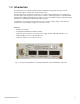
1.0 Introduction The AlphaNet™ Series Model XP-EDH-A2 External DOCSIS Transponder manages network powering through the existing cable modem infrastructure. A single transponder can monitor and manage one power supply and batteries. The transponder transmits data to a management system over the network’s existing infrastructure. Standard SNMP (Simple Network Management Protocol) provides access by any SNMP manager. Status Monitoring information is compatible with ANSI/SCTE HMS standards.
1.0 Introduction, continued 1.1 System Overview The XP-EDH-A2 is designed for use with the following standby power supplies: • XM2 • XM • AM/AP • ZTT, ZTT+ The transponder hardware is the same for all applications and harness kits are available for specific configurations. The XP-EDH-A2 receives data from a Universal Status Monitoring Card on XM/XM2 series power supplies, from the status monitor connector on Lectro ZTT power supplies, or from the RPM card on AM power supplies.
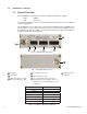
1.0 Introduction, continued 1.2 LED Indicators The front panel has four LEDs which indicate the following: POWER: Indicates device has power OFF: No power ON: Power on. (Battery harness connected to a battery string) ONLINE: Indicates a two-way RF (radio frequency) connection.
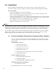
2.0 Installation Before installing the XP-EDH-A2 into a power supply, review your system requirements and determine the number of cable assemblies you need to monitor your HFC standby power supplies.
2.0 Installation, continued 2.1 General Installation Information for Supported Power Supplies, continued 2.1.1 Transponder Placement • • • • Place the transponder on the shelf inside the cabinet next to the power supply. Do not place the transponder on top of the power supply. Maintain access to the front of the transponder to ease the connection of the cables. Ensure the cabinet door can close without damaging the cables. Route and tie-wrap the cables in an orderly manner.
2.0 Installation, continued 2.1 General Installation Information for Supported Power Supplies, continued 2.1.5 Connecting the Power Supply Interface and Measurement Cables • • • Connect the power supply interface and measurement cables to the power supply. Connections are dependent on the type of power supply configuration you are using. See the section specific to your configuration. It is important to be able to measure the site input line voltage. If you are not using a USM2.
2.0 Installation, continued 2.1 General Installation Information for Supported Power Supplies, continued 2.1.9 Setting the DOCSIS Configuration File Options • • This step is performed at the network end of the installation. This file supplies the security and community string settings for the system, as well as the software upgrade parameters. Set the community strings, matching your DOCSIS cable modems. The following is an example: Sets Read-Write Community string.
3.0 Installation Instructions for Specific Power Supplies These are specific installation instructions for standby power supplies supported by the XP-EDH-A2 transponder. Each set of instructions include the interface card settings, a system diagram, and the output voltage calibration needed to successfully operate. NOTE: All settings and instructions specified here supercede information found in previous manuals. NOTE: When monitoring commercial line power, the XM2 (with the USM2.
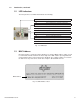
3.0 Installation Instructions for Specific Power Supplies, continued 3.1 Alpha XM2 Series, continued 3.1.1 USM2.5 Jumper Settings SW1 Settings: ON ON SW1 ON <48V and <20A ON 48V and <20A ON FRONT PANEL <48V and POWER SUPPLY CHASSIS > 20A 48V and > 20A Legend: ON Fig. 3-1, USM2.5 Switch/Jumper Settings NOTE: The switch settings in this section apply only to the EDH-A2 and differ from the EDH-A. Refer to the EDH-A Installation Manual for EDH-A installation procedures. 3.1.
3.0 Installation Instructions for Specific Power Supplies, continued 3.1 Alpha XM2 Series, continued 3.1.3 USM2 Jumper Settings JP2 (AC SCALING OF OUTPUT VOLTAGE) 1 2 3 JP1 (5V POSITION) ON ON POWER SUPPLY CHASSIS FRONT PANEL Legend: SW 1 ON SW 2 Pins jumpered Fig. 3-2, USM2 Settings for <48V and <20A JP2 (AC SCALING OF OUTPUT VOLTAGE) JP1 (5V POSITION) 1 2 3 ON FRONT PANEL POWER SUPPLY CHASSIS ON Legend: ON SW 1 SW 2 Pins jumpered Fig.
3.0 Installation Instructions for Specific Power Supplies, continued 3.1 Alpha XM2 Series, continued 3.1.3 USM2 Jumper Settings, continued JP2 (AC SCALING OF OUTPUT VOLTAGE) 1 2 3 JP1 (5V POSITION) ON ON POWER SUPPLY CHASSIS FRONT PANEL Legend: ON SW 1 SW 2 Pins jumpered Fig. 3-4, USM2 Settings for 48V and <20A JP2 (AC SCALING OF OUTPUT VOLTAGE) 1 2 3 JP1 (5V POSITION) ON ON POWER SUPPLY CHASSIS Legend: FRONT PANEL ON SW 1 Pins jumpered SW 2 Fig.
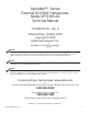
PWR POWER SUPPLY CABLE USM2 power supplies only 110V AC Line Input ( OPTIONAL ) SYSTEM RF CABLE IN 16 PIN 14 PIN 18 PIN Battery 0A C4 36 AlphaNet DOCSIS Transponder Power Supply R Power DS US ONLINE OUTPUT L N SSR OUTPUT 1 OUTPUT 2 ALARM ESC TEST UNLATCH RIBBON CABLE RETAINER BEFORE FULLY REMOVING MODULE.
3.0 Installation Instructions for Specific Power Supplies, continued 3.1 Alpha XM2 Series, continued 3.1.6 Provisioning the Network for the XM2 Series The transponder must be recognized by the CMTS as a valid device, be able to obtain an IP address and communicate with the SNMP management server. 1. Load the transponder’s MAC address into the CMTS. 2. Compile the two MIBs using a network manager or MIB browser software. 3. Setup SNMP using two proprietary MIBs files. 4.
3.0 Installation Instructions for Specific Power Supplies, continued 3.2 Alpha XM Series Power Supply NOTE: You may require a chipset upgrade for the USM and XM inverter drawer for proper operation with the XPEDH-A2. Operating an XM series power supply with the XP-EDH-A2 with the wrong version chipset firmware may result in intermittent or incorrect operation of the power supply. Contact your Alpha representative for additional information.
3.0 Installation Instructions for Specific Power Supplies, continued 3.2 Alpha XM Series Power Supply, continued 3.2.
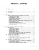
PWR POWER SUPPLY CABLE ONLINE US 16 PIN 14 PIN Red/Green wire Cut Here 18 PIN FOR XM SERIES ONLY CUT AND REMOVE A PIECE OF RED/GREEN WIRE IF PRESENT ! Black wire Side View 18 PIN Battery YELLOW WIRE Power Supply 0A C4 36 AlphaNet DOCSIS Transponder Power DS CUT THE WIRE Battery IN UPPER LEFT POSITION AS SHOWN. ANY WIRE COLOR.
3.0 Installation Instructions for Specific Power Supplies, continued 3.2 Alpha XM Series Power Supply, continued 3.2.4 Provisioning the Network for the XM Series The transponder must be recognized by the CMTS as a valid device, obtain an IP address, and communicate with the SNMP management server. 1. Load the transponder’s MAC address into the CMTS. 2. Setup SNMP using two proprietary MIBs files. 3. Compile the two MIBs onto a network manager or MIB browser software. 4.
3.0 Installation Instructions for Specific Power Supplies, continued 3.3 Alpha AM/AP Series Power Supply WARNING! Installing the XP-EDH-A2 transponder at an Alpha AM power supply site requires shutting down the power supply. If a short power interruption is not feasible, you must use an alternate source of system power during the installation of the transponder.
745-838-B2-001 Rev.
3.0 Installation Instructions for Specific Power Supplies, continued 3.3 Alpha AM/AP Series Power Supply, continued 3.3.2 Output Voltage Calibration No calibration is necessary for the Alpha AM/AP power supply. 3.3.3. Provisioning the Transponder on the Network The transponder must be recognized by the CMTS as a valid device and be able to obtain an IP address and communicate with the SNMP management server. 1. Load the transponder’s MAC address into the CMTS. 2.
3.0 Installation Instructions for Specific Power Supplies, continued 3.4 Alpha/Lectro ZTT+ Series Power Supply There are two models of the Lectro ZTT+ Series power supply inverter modules. You can easily identify one type from the other by checking the round 6-pin DIN connector located on the lower left side of the front panel: • Early units have a solid black DIN connector (pre-1998). • More current units have a silver band around the DIN connector.
Improper wiring may damage the unit and void the warranty.
745-838-B2-001 Rev.
3.0 Installation Instructions for Specific Power Supplies, continued 3.4 Alpha/Lectro ZTT+ Series Power Supply, continued 3.4.4 Alpha/Lectro ZTT+ Series Output Voltage Calibration No calibration is necessary for the ZTT+ Series power supplies. 3.4.5. Provisioning the Network for the Alpha/Lectro ZTT+ Series The transponder must be recognized by the CMTS as a valid device, obtain an IP address and communicate with the SNMP management server. 1. Load the transponder’s MAC address into the CMTS. 2.
4.0 Proprietary Management Information Bases (MIBs) You need to use two proprietary MIBs to successfully configure the XP-EDH-A2 to use the power supplies described in this manual. Compile these two MIBs onto a network manager or MIB browser software. To see a specific example of a MIBs file for a particular power supply, see that section of the manual. The objects available are: Object amDocsisDevicesTable amDocsisOPVoltageScaling Description Oid: 1.3.6.1.4.1.2183.2.3.3.1.
5.
6.0 Cable Selection Guide Interface cables : XM , XM2 power supplies CBL-PS-INTFC-01-003 CBL-PS-INTFC-01-003 (Alpha P/N 875-565-10) AM / AP power supplies CBL-PS-INTRFC-01-002 CBL-PS-INTFC-01-002 (Alpha P/N 875-564-10) T NEUT HO Lectro ZTT & ZTT+ power supplies CBL-PS-INTFC-02-005 (Alpha P/N 875-566-10) GR CBL-PS-INTFC-02-005 TA OU ND MPE R ZT T Z SILTT+ VE Z R BLTT+ AC K 3 POSITION SWITCH 745-838-B2-001 Rev.
6.
6.0 Cable Selection Guide, continued Line Voltage Cables: 120VAC TO 9VAC XM , XM2 , AM/AP, 120Va c CBL-PS-PWR-01-001 Alpha P/N 875-563-10 220VAC TO 9VAC XM , XM2 , AM/AP, 220Va c CBL-PS-PWR-03-002 Alpha P/N 875-562-10 220V US NEMA 6-15P IEC C13 3 FT CORD Lectro ZTT, ZTT+, 120Vac CBL-PS-PWR-02-002 Alpha P/N 875-718-10 120VAC TO 9VAC Lectro ZTT, ZTT+, 220Vac CBL-PS-PWR-04-001 Alpha P/N 875-717-10 220VAC TO 9VAC IEC C13 220V US NEMA 6-15P 3 FT CORD 745-838-B2-001 Rev.
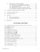
7.0 Dimensions and Specifications 7.1 Dimensions of XP-EDH-A2 1.26" 9.42" (overall) 4.55" 8.75" Alpha P/N: 745-838-10-004 Model No: XP-EDH-A22 MAC ID: XXXXXXXXXXXX S/N: XXXXXXXX Attention • This transponder measures scaled AC output voltage. • Verify the XM-USM or XM2-USM2/USM2.5 is configured for scaled AC output. ONLINE R US 0A C4 36 AlphaNet DOCSIS Transponder DS PWR 1.26" Power Power Supply Batteries Fig. 7-1, Outline Dimensions, XP-EDH-A2 36 745-838-B2-001 Rev.
7.0 Dimensions and Specifications, continued 7.2 Battery Cable Wiring Diagram CAUTION! The following diagram shows wiring to three batteries using a six battery cable. Installation Note: The + battery terminals face the front of the enclosure BATTERY STRING 1 BATTERY 2 2V 1+1 BATTERY 3 4V 1+2 D RE BATTERY 1 +V BATT TEMP PROBE RED BLACK BLACK V 24 2+ 2+12V -V PLACE TEMP PROBE BETWEEN BATTERIES BATTERY CABLE CBL-PS-BAT-06-004 Fig. 7-2, Battery Cable Wiring Diagram 745-838-B2-001 Rev.
8.0 Specifications General Speci cations Hardware General Model: Power Supplies Supported: XP-EDH-A2 XM2 (requires USM2 or USM2.5) XM (requires USM) AM (requires APM card) Lectro ZTT, ZTT+ DOCSIS 2.
Power Alpha Technologies ® Alpha Technologies 3767 Alpha Way Bellingham, WA 98226 USA Tel: +1 360 647 2360 Fax: +1 360 671 4936 Web: www.alpha.com Alpha Technologies Ltd. 4084 McConnell Court Burnaby, BC, V5A 3N7 CANADA Tel: +1 604 430 1476 Fax: +1 604 430 8908 Alpha Technologies Europe Ltd.