
User Manual

30
745-419-C0-002, Rev. B
DOCSIS® Network Power Monitoring
General Specifi cations
General
Power Supplies
Supported:
XM2 using USM2 or USM2.5 XM/AM us-
ing USM/RPM, ZTT, ZTT+, Generic
DOCSIS Compat-
ibility:
Firmware DOCSIS 1.1
Monitoring Protocol: SNMPv1
Devices Monitored: Power Supply, Batteries and Generator
(analog status approximates ANSI/SCTE
25-3 2002, formerly HMS 022)
RF Transmit / Receive
Tx Frequency
Range:
5 to 42 MHz
Output Power: +8 to +58 dBmV
Channel Bandwidth: 6 MHz
Receive Center
Freq Range:
91 to 857 MHz (Standard, HRC, IRC
channels)
Input Level: -15 to +15 dBmV
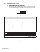
Monitored Parameters
Power Supply Data:
Model XM2 XM/
AM
ZTT/
ZTT+
Other1
Output Voltage X X X X
Battery Voltage X X X X
Output Current X X X X
AC Line Voltage X X X X
Standby/AC Line
Fail
XXX
Equipment/Test Fail X X
Output Fail X X
Enclosure Door X X X X
Test (Control) X X X
Cabinet Temp. X X X X
Notes: 1) This option enables monitoring or basic information
from power supply models not listed.
Number of Battery
Strings:
1-4 Strings of 24V, 36V or 48V
Battery Data: Individual Battery Voltages
Generator Control: Remote test (start/stop)
Generator Data: (Requires AlphaGen generator system with
ECM status interface)
Major Alarm (Consists of: Low Oil Pressure, Engine Over-temp,
Engine Over-speed, Crank Limit, Over Voltage, Low Fuel, Water
Intrusion, Pad Shear, Gas Hazard, Test Fail)
Minor Alarm (Consists of: Control Fail, Alternator Fail, Low Igni-
tion Battery Voltage, Manual Bypass Active, Enclosure Door, DC
Voltage Tolerance, Engine Disabled, Service Required)
Engine Alarm (Consists of: Low Oil Pressure, Engine Over-temp,
Engine Over-speed, Crank Limit, Engine Disabled)
Gas Hazard
Enclosure Alarm
Test Status (pass/fail)
Enclosure Door (open/closed)
Management
NMS/EMS: Cheetah™ DOCSIS® Power Supply Management
Software Standard SNMP Management Tools
HMS MIBs: Power Supply (ANSI/SCTE 38-4) Generator (ANSI/
SCTE 38-6)Transponder (ANSI/SCTE 38-3) Alarm/Trap (ANSI/
SCTE 38-1 and 38-2)
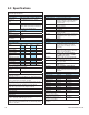
5.0 Specifi cations
Hardware
RF Cable Interface: F-connector, female, 75 ohm
Local Interface: RJ-12, RS-232, 19.2kb,N,8,1 Requires
serial port adapter and PC with terminal
emulation software (Hyper-Terminal
recommended)
LED Indicators: RF Transmit
RF Receive/Link
Transponder Ready
Local Data
Environmental: -40ºC to +65ºC 10% to 90% non-con-
densing humidity
Emissions: EN50022 Class A and FCC Part 15 Class
A (Installed in power supply enclosure
system)
Warranty: 2 years
Dimensions: 4.6”D x 5.75”W x 1.5”H
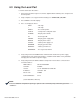
Ordering Information
745-419-20 DOCSIS Analog Transponder with VoIP
Test Functions Order power supply
interface cable and battery sense kit
separately.
745-419-22 DOCSIS Analog Transponder, Dual IP
Order power supply interface cable and
battery sense kit separately.
875-335-20 Interface cable for monitoring XM2
with USM2 (120/240VAC) or USM2.5
(120VAC) status interface
875-335-21 Interface cable for monitoring XM/AM
with USM/RPM status interface
875-335-22 Interface cable for monitoring ZTT or
ZTT+ (post 1998)
875-335-23 Interface cable for monitoring ZTT+ (pre-
1998 versions)
875-335-24 XM2 with USM2.5 (240VAC input)
875-335-25 Interface kit for monitoring other power
supplies not listed herein. Contact Alpha
for details.
875-349-10 Local port adaptor
Battery Sense Wire Kits:
XP-BSC-24-2-6 1x24V, 6’ 875-401-20
XP-BSC-24-4-6 2x24V, 6’ 875-401-21
XP-BSC-24-2-9 1x24V, 9’ 875-401-22
XP-BSC-24-4-9 2x24V, 9’ 875-401-23
XP-BSC-3-6 1x36V, 6’ 874-842-21
XP-BSC-3-9 1x36V, 9’ 874-842-27
XP-BSC-6-9 2x36V, 9’ 874-842-28
XP-BSC-4-6 1x48V, 6’ 874-841-21
XP-BSC-8-6 2x48V, 6’ 874-841-20
XP-BSC-4-9 1x48V, 9’ 874-841-25
XP-BSC-8-9 2x48V, 9’ 874-841-24
RTS
(Required in cabinets with
tamper using screw terminals)
745-178-21
Tamper Wire Kit 845-494-20
Vin 120V Sense
(Required for all
applications except USM2.5)
875-493-21
Extended wire lengths available. Contact Alpha for ordering
information.