
User Manual

23745-419-C0-002, Rev. B
1. Generator Interface, Alpha P/N 874-975-20
2. Battery Sense Kit See Sec. 5.0 for list
3. Ignition Battery/
Aux Power Cable,
Alpha P/N 874-976-20
4. Power Supply Interface See Sec. 5.0 for list
5. Battery Sense Kit See Sec. 5.0 for list
6. Craft Port Cable Alpha P/N 875-349-10
7. RTS Cable Alpha P/N 745-178-21
8. Vin Sense Alpha P/N 875-493-21
1
2
3
7
5
4
8
6
Logic Level
Converter
Alpha P/N 875-349-10
To Battery String
A and B
To Generator Starter Battery
To Auxiliary Power
To Power Supply
To Battery String
C and D
To RTS
LCL
RDY
PWR SPLY
RF
GEN
BAT C/D
BAT A/B
AUX PWR
LOCAL
RX
TX
1
1
1
CM: 00:10:3F:XX:XX:XX
P/N: 745-419-20-XXX
S/N: XXXXXX
1
1
To Generator
Surge Suppresser
Ground Block
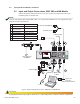
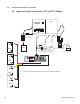
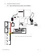
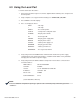
Fig. 2-6, Input and Output Connections, XM2, XM, and AM Models
2.0 Transponder Installation, continued
2.5 Input and Output Connections, XM2, XM, and AM Models
Connect the battery string or Aux Power connector to power the transponder. Connect the
remaining cables as shown below.
A ground block with surge suppression device is required to protect sensitive electronic components.
CAUTION!
Verify the transponder cable modem MAC address is recorded in the CMTS before connecting the RF cable
and powering up the transponder.
NOTE: