
User Manual

22
745-419-C0-002, Rev. B
2.0 Transponder Installation, continued
2.4 Power Supply Interface Connection, continued
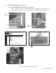
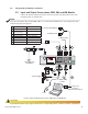
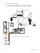
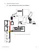
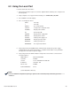
Connect the Interface cable to the USM, USM2, USM2.5 or RPM card as shown below. Verify
that pin 1 lines up with pin 1 on the connector (furthest from the 2 pin tamper connector).
Pin 1
Fig 2-5, Power Supply Interface Connections
XP Series with USM
AM Power Supply with RPM Card
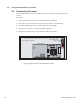
Side View of Connector
XM2 Series with USM-2 or USM2.5
Pin 1
Pin 1
Tamper
Connector
Tamper
Connector
Sheet Metal
USM, USM2 or USM2.5 Circuit Board
Transponder Connector
Power Supply Interface Cable
From DOCSIS Transponder