
User Manual

21745-419-C0-002, Rev. B
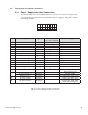
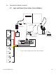
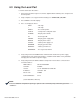
Table 2-3, Power Supply Interface Connection
2.0 Transponder Installation, continued
2.4 Power Supply Interface Connection
The table below describes the POWER SUPPLY connector. The interface confi g bits (pins
7,8, and 9) allow the transponder to monitor different power supplies, and provide varying
monitoring capabilities.
Back of Plug
12
345678
910
11 12
13
14
15 16
Pin Description Type States
(Active State in BOLD)
Scaling
1 (GND) Reference Return
2 Inverter Test/Reset Digital Out Low/High
3 RTS Power Analog Out +5V Power to RTS
4 Tamper Status Digital In High/Low
5 Output Fail Alarm Digital In High/Low
6 Equipment Fail Alarm Digital In High/Low
7 Interface Confi g Bit 1 Digital In Open/Ground
8 Interface Confi g Bit 2 Digital In Open/Ground
9 Interface Confi g Bit 3 Digital In Open/Ground
10 Output Current 1 Analog In 0.4VDC/1A AC (AM, XM, XM2)
11 Output Current 2 Analog In 0.4VDC/1A AC (XM2 Only)
12 Standby/Line Fail Analog In High/Low
13 RTS Analog In 2.98VDC @ 25ºC,
10µV change per ºC
14
AC Input Voltage -or- Analog In 0-2.8Vpk (XM2)
Output Current 1 Analog In 0.1VDC/1A AC (ZTT option)
15 AC Input Voltage Analog In 0.1VAC/1VAC (ZTT option)
16 AC Output Voltage Analog In
0.5VAC/1VAC (XM, XM2)
1VAC/1VAC (ZTT option)