AlphaNet™ Series External DOCSIS® Analog Transponder Technical Manual Effective: January, 2006 Alpha Technologies
Power Alpha Technologies ®
External DOCSIS® Analog Transponder Technical Manual 745-419-C0-002, Rev. B Effective Date: January, 2006 Copyright © 2006 Alpha Technologies, Inc. member of The GroupTM NOTE: Alpha denies responsibility for any damage or injury involving its enclosures, power supplies, generators, batteries or other hardware, manufactured by Alpha or members of the Alpha Group, when used for an unintended purpose, installed or operated in an unapproved manner, or improperly maintained.
Table of Contents Safety Notes .......................................................................................................................... 6 1.0 2.0 3.0 4 Introduction to the DOCSIS Transponder ................................................................... 7 1.1 System Overview ............................................................................................. 8 1.2 LED Indicators ...........................................................................................
List of Figures Fig. 1-1, DOCSIS External Analog Transponder ........................................................ 7 Fig. 1-2, Basic System Block Diagram ....................................................................... 8 Fig. 1-3, LEDs ............................................................................................................. 9 Fig. 2-1, 24VDC Battery Sense ................................................................................ 16 Fig. 2-2, 36VDC Battery Sense ..........
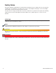
Safety Notes Review the drawings and illustrations contained in this manual before proceeding. If there are any questions regarding the safe installation or operation of the system, contact Alpha Technologies or the nearest Alpha representative. Save this document for future reference. To reduce the risk of injury or death and to ensure the continued safe operation of this product, the following symbols have been placed throughout this manual. Where these symbols appear, use extra care and attention.
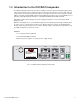
1.0 Introduction to the DOCSIS Transponder The DOCSIS Analog Transponder provides the ability to manage network powering through existing cable modem infrastructure. A single transponder can monitor and manage a power supply, batteries, and generator. The transponder transmits data to a management system over the network’s existing CMTS, and using standard SNMP (Simple Network Management Protocol) keeps bandwidth use to a minimum. Status Monitoring information is compatible with ANSI/SCTE HMS standards.
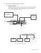
1.0 Introduction to the DOCSIS Transponder, continued 1.1 System Overview The DOCSIS Analog Transponder receives data from a Universal Status Monitoring Card on XM series power supplies, from the status monitor connector on Lectro ZTT power supplies, or from the RPM card on AM power supplies. The transponder and power supply can be network managed through your existing CMTS.
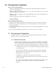
1.0 Introduction to the DOCSIS Transponder, continued 1.2 LED Indicators AUX PWR 1 TX LCL RX RDY LOCAL TX: Indicates status of data transmission to CMTS. OFF: Idle Status. Flickering ON: Communicating with CMTS. LCL: Indicates the status of the local Craft port. OFF: No communication. ON flickering OFF: Ongoing communication. RDY: Indicates operation status of the transponder. Flashing ON and OFF: Normal Operation. OFF: No power or malfunctioning transponder. ON: Transponder reset in progress.
2.0 Transponder Installation Steps to a Successful Installation: • Operator’s IT Department must allow the transponder’s Cable Modem (CM) to obtain an IP address from the DHCP Server. • Operator’s IT Department must load the hmsinit.ini file on the TFTP Server, or use the cable modem config file (see section 2.1.3). • Operator’s network security policies must allow SNMP traffic to pass between transponder and SNMP manager. • Install the transponder and any related equipment in the enclosure.
2.0 Transponder Installation, continued 2.1 Provisioning the Transponder, continued 2.1.2 Transponder Configuration Using the HMS.INI File The transponder’s cable modem, at first power-up or reset command, requests a configuration file from the TFTP server. The file must contain the IP address of the SNMP manager. It may also contain up to five additional SNMP trap recipients. The SNMP manager is the only device that can perform SNMP set/get/get-next commands.
2.0 Transponder Installation, continued 2.1 Provisioning the Transponder, continued 2.1.2 Transponder Configuration Using the HMS.INI File, continued NOTES: 12 • The “//” characters indicate an optional comment line. • Please note that there is only one each and a (cursor return and line feed) at the end of every section. • There must also be only one and only one past the last character at the end of the file. • The identifiers (in brackets) must be in upper-case.
2.0 Transponder Installation, continued 2.1 Provisioning the Transponder, continued 2.1.3 Transponder Configuration Using Cable Modem Config File To eliminate the hmsinit.ini configuration file, a select set of MIB variables must be added to the cable modem config file. These MIB variables contain the initialization parameters that replace the hmsinit.ini file. If the parameters are not set in the cable modelm config file, the code will fall back to its previous operation and attempt to load an hmsinit.
2.1 Provisioning the Transponder, continued 2.1.3 Transponder Configuration Using CM Config File, continued The following table lists the OID’s from the MIB for each parameter. In case of any discrepancy the MIB itself should be considered correct. This is included as a reference for creating the cable modem config files. TLGDHMSInit MIB PARAMETER OID TYPE VALUE SERVER IP 1.3.6.1.4.1.2082.5.1.1.1.1.0 IP address Dotted decimal IP Eg. 172.16.3.42 TIME SERVER IP 1.3.6.1.4.1.2082.5.1.1.1.2.
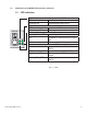
2.0 Transponder Installation, continued 2.2 Battery Sense Cable and Aux Power Connections The battery sense cable (BSC) is used for battery sensing and for powering the transponder. Acceptable voltages are 20-60VDC. Install the cables as shown in the following diagrams. The Aux Power connection is only needed when the battery pack is greater than 15 feet from the transponder. CAUTION! Verify battery connections are correct prior to applying power.
2.0 Transponder Installation, continued 2.
Transponder Installation, continued 2.2 Battery Sense Cable and Aux Power Connections, continued 36V Systems NEG NEG 3A 2A 2 7 3 8 4 874-842-21 (6') 874-842-27 (9') POS Vbatt 3A [C] 36V (pin 4) 6 A/B [C/D] NEG (pin 1) 1 1A POS Vbatt 2A [C] 24V (pin 3) POS 5 NEG Vbatt 1A [C] 12V (pin 2) 2.
2.0 Transponder Installation, continued 2.
2.0 Transponder Installation, continued 2.2 Battery Sense Cable and Aux Power Connections, continued Use the Aux Power connector to connect the ignition battery sense and auxiliary power connections when the battery strings are located more than 15 feet from the transponder. The Generator Ignition Battery Sense cable must be connected as shown below. Connect the Aux Power connector where the red and black cables leading to the power supply are connected.
2.0 Transponder Installation, continued 2.3 Power Supply Communication Card Settings The power supply communication card settings determine the digital/analog setup and scaling that affect how information is reported to your network management system. Refer to your power supply’s communication card settings to be certain that your communication card is set up correctly. The following table is for reference only.
2.0 Transponder Installation, continued 2.4 Power Supply Interface Connection The table below describes the POWER SUPPLY connector. The interface config bits (pins 7,8, and 9) allow the transponder to monitor different power supplies, and provide varying monitoring capabilities.
2.0 Transponder Installation, continued 2.4 Power Supply Interface Connection, continued Connect the Interface cable to the USM, USM2, USM2.5 or RPM card as shown below. Verify that pin 1 lines up with pin 1 on the connector (furthest from the 2 pin tamper connector). Tamper Connector Pin 1 Pin 1 Tamper Connector XM2 Series with USM-2 or USM2.5 XP Series with USM Power Supply Interface Cable From DOCSIS Transponder Sheet Metal Transponder Connector USM, USM2 or USM2.
2.0 Transponder Installation, continued 2.5 Input and Output Connections, XM2, XM, and AM Models Connect the battery string or Aux Power connector to power the transponder. Connect the remaining cables as shown below. NOTE: Verify the transponder cable modem MAC address is recorded in the CMTS before connecting the RF cable and powering up the transponder. 1. Generator Interface, Alpha P/N 874-975-20 2. Battery Sense Kit See Sec. 5.0 for list 3.
2.0 Transponder Installation, continued 2.6 Input and Output Connections, ZTT and ZTT+ Models ZTT/+ RTS Cable Alpha P/N 745-178-21 Vout/Iout Sense Alpha P/N 875-456-10 Vin Sense #4 48V SPI Power Supply Interface Cable Alpha P/N 875-335-22 (ZTT & ZTT/+ post 1998) Alpha P/N 875-335-23 (ZTT/+ pre 1998) #3 BAT A/B R F 1 1 36V 1 PWR SPLY BAT C/D Tamper Wire Kit Alpha P/N 875-494-20 AUX PWR 1 TX LOCAL RX Battery Sense Cable Kits (see Section 5.0) #2 24V Fig.
2.0 Transponder Installation, continued 2.7 Input and Output Connections, Generic Models RTS Cable Alpha P/N 745-178-21 Vout/Iout Sense Alpha P/N 875-456-10 Vin Sense #4 48V SPI Power Supply Interface Cable Alpha P/N 875-335-25 #3 BAT A/B R F 1 1 36V 1 PWR SPLY BAT C/D Tamper Wire Kit Alpha P/N 875-494-20 AUX PWR 1 TX LOCAL RX Battery Sense Cable Kits (see Section 5.0) #2 24V Fig. 2-8, Input and Output Connections, Generic Models #1 12V 745-419-C0-002, Rev.
2.0 Transponder Installation, continued 2.8 Transponder Placement Place the transponder in the power supply section of the enclosure away from other heat sources. Procedure: 1. Connect all cables to the front of the transponder before mounting. 2. Select an area on the right side of the enclosure if possible (as shown below). 3. Test fit the transponder to ensure that the cables are long enough. 4. Clean the area to ensure a strong bond with the adhesive.
2.0 Transponder Installation, continued 2.9 Local and RF Connectors The Local connector allows the technician to communicate with the transponder and power supply through a PC’s RS-232 serial port. The RF connector is the primary I/O port to the CMTS. AUX PWR AT A/B RF 1 1 D Tra TX LCL RX RDY AT C/D LOCAL Fig. 2-10, Local Port Fig. 2-11, RF Connection 2.10 Verify Transponder Operation During initial transponder power-up, the RDY LED will be on solid. 745-419-C0-002, Rev.
3.0 Network/Element Management Software 3.1 Provisioning the SNMP Manager The following MIB (Management Information Base) files are required for the SNMP Manager to collect data from the transponders. These files can be found on the Society of Cable Telecommunications (SCTE) web site www.scte.org.
4.0 Using the Local Port Local Port Connection Procedure: 1. Connect the RS-232 to logic level converter (Alpha P/N 875-349-10) to the computer and the transponder. 2. Setup computer to use Hyper-Terminal. Settings are: 19200 baud, 8, N, and 1. 3. Press ENTER to view the display. 4.
5.0 Specifications DOCSIS® Network Power Monitoring General Specifications General Power Supplies Supported: DOCSIS Compatibility: Monitoring Protocol: Devices Monitored: XM2 using USM2 or USM2.5 XM/AM using USM/RPM, ZTT, ZTT+, Generic Firmware DOCSIS 1.
Power Alpha Technologies ® Alpha Technologies 3767 Alpha Way Bellingham, WA 98226 USA Tel: +1(360) 647 2360 Fax: +1(360) 671 4936 Web: www.alpha.com Alpha Technologies Ltd. 4084 McConnell Court Burnaby, BC, V5A 3N7 CANADA Tel: +1(604) 430 1476 Fax: +1(604) 430 8908 Alpha Technologies Europe Ltd.