
User Manual

73
746-257-B5-001, Rev. A1 (11/2013)
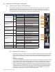
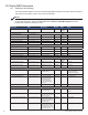
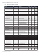
Fig. 9-4, LED Functionality and Indications
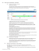
9.3 System Status Indicators and Reset Button
The IDH4 Series indicates status with light emitting diodes (LEDs). During system start up, the LEDs
will rst blink momentarily then indicate the current status of a variety of parameters on the IDH4
Series transponder. The LEDs indicate alarms, RF power level status, battery string connectivity and
communications activity with the network. A description of each LED follows.
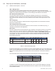
LED Status Behavior Indication
ALM/RDY: Alarm and Ready
N/A OFF No power or malfunctioning IDH4 Series
GRN
ON Reset of the IDH4 Series is in process
Steady Blinking Normal operation
RED
Blinking more OFF than ON Minor Alarm SCTE-HMS congured
Blinking more ON than OFF Major Alarm SCTE-HMS congured
REG: Upstream ranging and
registration lock.
GRN
OFF No power, upstream frequency undetermined
OFF / ON
Power on, downstream locked, upstream frequency
ranging, DHCP request in progress
ON CMTS registration completed
DS: Downstream RF Carrier
detection and lock.
GRN
OFF No power / downstream carrier
OFF / ON Power on, downstream carrier frequency searching
ON Downstream carrier lock
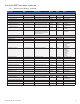
ACT: CPE Activity status GRN
OFF No Ethernet communications activity
OFF/ON
Momentary ash while CPE communications
ongoing via the Ethernet Craft port
LNK: CPE Link status GRN
OFF No Ethernet link
ON Link on Ethernet Craft port
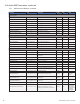
RF Rx/Tx Power Level
Indicator
TRI
OFF No RF detected
Blue
Rx/Tx Power at a warning level as set within the
SCTE-HMS Property Table
Green Rx/Tx RF Power level within tolerance
Red
Rx/Tx Power at an alert level as set within the
SCTE-HMS Property Table
COM: AlphaBus
Communications
GRN
OFF No AlphaBus Communications
OFF/ON
Momentary ashes - AlphaBus Port Communications
active
BATT A/B GRN ON/OFF ON (steady) if battery string(s) connected correctly
BATT C/D GRN ON/OFF ON (steady) if battery string(s) connected correctly
9.0 Start Up and Verication, continued
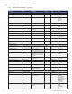
9.3.1 Detailed LED Descriptions
After power is applied or a reset occurs, all LEDs will ash in certain patterns indicating the cable
modem chipset is starting or restarting. Once it is ready, it will begin the DOCSIS requirement of
searching for the downstream frequency lock and the LEDs will follow the detailed descriptions
below.
ALM/RDY - Alarm/Ready
The LED blinks GREEN during normal operation. The frequency of ashing by this LED provides
a visual alert for power supply discrete major and minor alarms if congured in the property and
discrete property tables of the SCTE-HMS MIB. If an event triggers an HMS alarm, the ALM/
RDY LED blinks RED according to the alarm type until the alarm has been resolved. For minor
alarms, the frequency of ashing will be more OFF than ON, and for major alarms the frequency
of ashing will be more ON than OFF. If both minor and major alarms activate, the ALM/RDY
LED displays a major alarm signal. Refer to Section 6.3, The Alpha MIBs for information on
conguring the IDH4 Series for active monitoring and alarming.
ALM/RDY
REG
ACT
LNK
RF
BATT A/B
BATT C/D
COM
DS