
User Manual

62
746-257-B5-001, Rev. A1 (11/2013)
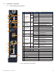
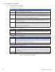
Item LED or Connector Status Behavior Indication
1
ALM/RDY: Alarm and
Ready
N/A OFF No power or malfunctioning transponder
GRN
ON Transponder reset in process
Steady Blinking Normal operation
RED
Blinking more
OFF than ON
Minor Alarm
Blinking more
ON than OFF
Major Alarm
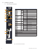
2
REG: Upstream
ranging and
registration lock
GRN
OFF No power, upstream frequency undetermined
BLINKING
Power on, downstream locked, upstream
frequency ranging, DHCP request pending
ON CMTS registration completed
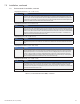
3
DS: Downstream RF
Carrier detection and
lock
GRN
OFF No power / downstream carrier
BLINKING Power on, downstream carrier frequency searching
ON Downstream carrier lock
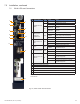
4
ACT: CPE Activity
status
GRN
OFF No Ethernet communications activity
BLINKING
Momentary ashes during CPE communications
via the Ethernet Craft port
5 LNK: CPE Link status GRN
OFF No link
ON Link on Ethernet Craft port
6
RF Rx/Tx Power Level
Indicator
TRI
OFF No RF detected
Blue
Rx/Tx Power at a warning level as set within the
SCTE-HMS Property Table
Green Rx/Tx RF Power level within tolerance
Red
Rx/Tx Power at an alert level as set within the
SCTE-HMS Property Table
7 BAT A/B GRN ON/OFF ON (steady) if battery string(s) connected correctly.
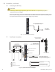
8 BAT A/B Connector
9 RST: Reset buttton
10 TPR: Tamper Switch connector
11 ETH: Ethernet connection
12 RF Connection
13 CM, CPE MAC Address label
9
10
11
1
2
3
7
4
5
6
12
13
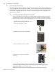
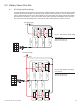
Fig. 7-5, IDH4 LEDs and Connectors
7.4 IDH4 LEDs and Connections
7.0 Installation, continued
8