
User Manual

52
746-257-B5-001, Rev. A1 (11/2013)
6.2.3 General Power Supply Alarms
The Intelligent CableUPS detects a wide array of alarms and displays the type of active alarm in the
Smart Display screen and the severity of alarm (e.g., Major/Minor) by means of the Inverter Module LEDs.
6.0 Data Management, continued
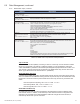
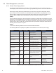
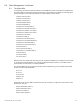
Active Alarm Alarm type Alarm Category Probable Cause of Alarm Corrective action
SELF TEST FAIL Major PWR
Output voltage failed or batteries less than
1.85V/C during Self Test.
1. Check Batteries
2. Check Inverter
LINE ISOLATION RELAY Major PWR
Line isolation has failed and Inverter
operations are suspended.
1. Replace Power Supply as soon as possble
OUTPUT FAIL Major PWR
The AC output has failed due to a bad Inverter
or transformer.
1. Check Conguration
2. Replace Inverter
3. Replace Power Supply
OUTPUT OVERLOAD Major PWR The output is overloaded or shorted.
1. Remove Short Circuit
2. Reduce Output Load
3. Replace Power Supply
OUTPUT 1 TRIPPED Major PWR
Output 1 AlphaDOC hardware protection
mode is engaged and overloaded.
1. Reduce Output Load
2. Check AlphaDOC setting
OUTPUT 2 TRIPPED
Major PWR Output 2 AlphaDOC hardware protection
mode is engaged and overloaded.
1. Reduce Output Load
2. Check AlphaDOC Setting
CHARGER FAILURE Major PWR
Charger has failed to shut down; possible
battery over temperature condition exists.
1. Re-seat Inverter
2. Perform Self Test
3. Replace Inverter
INVERTER TEMP Major PWR
Inverter heat sink has exceeded set
temperature. (Stand-by operations suspended
until temperature drops to a safe level.)
1. Check Ventilation
2. Replace Inverter
CONFIG ERROR Major PWR
The power supply is improperly congured
and operation is suspended until error is
corrected.
1. Check Inverter Module
INPUT FAIL Minor PWR Utility AC input has failed.
1. Check AC Input
2. Restore AC Input
3. Connect Generator
INPUT CURRENT LIMIT Major PWR
AC Input current exceeds threshold setting.
1. Reduce Output Load
2. Check Input Current Limit Setting
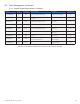
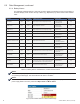
Table 6-6, Power Alarms: Classications, Causes and Corrections
General power supply alarms are passed directly from the power supply to the transponder without
specic denition and are classied in the HMS MIB table as psMinorAlarm and psMajorAlarm. There
are a number of problems that can generate these alarms and the exact nature of the situation is not
specied. Minor and Major alarms are dened by the SCTE standards committee as follows:
psMajor
“Service has been dropped or a service interruption is imminent. Indicates that an immediate truck roll is
appropriate.” Several psMajor alarms are latching, meaning that the alarm won’t clear until the problem is
xed and after a successful completion of a Self Test. A Self Test is the preferred method of verifying the
resolution of the alarm condition as cycling the power has the potential of masking the problem and not
indicating the actual state of the system.
psMinor
“A non-service affecting condition has occurred and should be monitored.”
The following table lists the psMajor and psMinor alarm denitions for the XM3-HP power supply.