
User Manual

48
746-257-B5-001, Rev. A1 (11/2013)
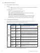
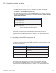
6.2.1 SCTE-HMS Congurable Alarms, continued
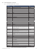
Table 6-3, Recommended Settings for IDH4 Series Analog Alarms
Analog Alarms and Common Settings
Analog Alarms Description
Alarm
Enable
LOLO LO HI HIHI Deadband
psTotalStringVoltage
36V Scaled representation of the full
battery string in 1/100 Volts units
0x0F 3300 3500 4520 4570 50
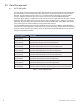
psBatteryVoltage
Battery Voltage of individual
batteries, scaled 1/100 Volts units
0x0F 1050 1150 1530 1550 20
psInputVoltage
120V Scaled representation of the input
line voltage in 1/100 Volts units
0x0F Varies by site. The XM3-HP will switch to standby
at nominal +15% -20%
220V 0x0F
psOutputVoltage
60V Scaled representation of the
power supply output voltage in
1/100 Volts units
0x0F 5650 6000 6600 7000 200
90V 0x0F 7800 8200 9150 9300 200
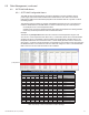
psPowerOut
Representation of power supply
output power in 1W units
0x00 It is recommended that psOutputCurrent be used
for output alarms.
psStringChargeCurrent
Battery string charge current,
scaled in 1/100 Amp units
0x0C Disable Disable 1200 1250 20
psStringFloat
Battery string oat charge current,
scaled in 1/100 Amp units
0x0C Disable Disable 1200 1250 20
psOutputCurrent
15A 0x0C Disable Disable 1650 1720 20
18A 0x0C Disable Disable 1980 2060 20
22A 0x0C Disable Disable 2420 2530 40
24A 0x0C Disable Disable 2640 2750 40
psTemperature -40 to +80 degrees C 0x0F Varies by site
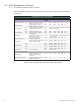
Alarms for Optional Generator
GenVBatIgnition
Scaled representation of the
generator's ignition battery in
1/100 Volts
0x0F 1150 1200 1500 1550 20
genEnclosureTemperature
Temperature inside generator's
enclosure in degrees C
0x09 -40 0 0 55 5
The following table displays the various analog alarms with common settings for the IDH4 Series
Transponder.
6.0 Data Management, continued