AlphaNet™ IDH4 Series DOCSIS® Status Monitor for the XM3-HP CableUPS® Technical Manual Effective: November 2013
Power Alpha Technologies ®
AlphaNet™ IDH4 Series DOCSIS® Status Monitor for XM3-HP CableUPS® Technical Manual 746-257-B5-001, Rev. A1 Effective Date: November 2013 Copyright© 2013 Alpha Technologies, Inc. member of The GroupTM NOTE: Alpha denies responsibility for any damage or injury involving its enclosures, power supplies, generators, batteries or other hardware, manufactured by Alpha or members of the Alpha Group, when used for an unintended purpose, installed or operated in an unapproved manner, or improperly maintained.
Contents Safety Notes ......................................................................................................................................7 1.0 Introduction.....................................................................................................................................8 2.0 Overview 2.1 2.2 2.3 2.4 ....................................................................................................................................10 System Diagram.................
Contents, continued 6.2.3 General Power Supply Alarms..............................................................................52 6.2.4 Battery Alarms.......................................................................................................54 6.3 The Alpha MIBs...........................................................................................................55 6.3.1 The Alpha MIB Structure.......................................................................................
Figures Fig. 1-1, AlphaNet IDH4X....................................................................................................................... 8 Fig. 1-2, AlphaNet IDH4.......................................................................................................................... 8 Fig. 1-3, AlphaNet IDH4L........................................................................................................................ 8 Fig. 1-4, Side View, AlphaNet IDH4 Series.....................
Tables Table 1-1, IDH4 Series Transponder Model Variation............................................................................ 8 Table 2-1, LEDs and Indications........................................................................................................... 12 Table 3-1, Modem Community String Parameters................................................................................ 14 Table 3-2, Trap Destination Addresses.....................................................................
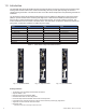
1.0 Introduction The AlphaNet IDH4 Series Embedded DOCSIS Transponder allows monitoring of Alpha power supplies through existing cable network infrastructure. Advanced networking services provide quick reporting and access to critical powering information. This manual focuses on the IDH4 Series transponders complementing the XM3-HP CableUPS. The IDH4 Series utilizes Simple Network Management Protocol (SNMP) and Management Information Bases (MIBs) to provide network status monitoring and diagnostics.
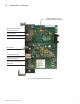
1.0 Introduction, continued Intelligent CableUPS Interface (located on other side of the board) Environmental IO Connector (IDH4X and IDH4L only) Tamper Connector Ethernet Port for Local Diagnostics RF Connector COM Port (IDH4X only) Battery Monitoring Connection A/B (IDH4 and IDH4X only) Battery Monitoring Connection C/D (IDH4X only) Fig. 1-4, Side View, AlphaNet IDH4 Series 746-257-B5-001, Rev.
2.0 Overview 2.1 System Diagram 10 SNMP-based Network Management System 2 IDH4 Series 1 Power Supply 5 Coax/HFC Network 6 CMTS 12 TCP/IP Network 4 Local Computer 3 External Generator 7 DHCP Server 8 TFTP Server 9 TOD Server 11 Web Browser Fig. 2-1, Representative System Arrangement 1 2 3 The IDH4 Series contains both SCTE-HMS Management Information Base (MIBs) and the proprietary Alpha MIB tables.
2.0 Overview, continued 2.2 Network Connectivity The IDH4 Series cable modem must be recognized by the CMTS as a valid device to be assigned an IP address from the DHCP server, to locate the TFTP and TOD servers, and to communicate with the SNMP management server (trap receiver). Data from both the cable modem and power supply are accessed and managed through the modem’s IP address on the secure private modem network.
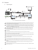
2.0 Overview, continued IDH4 Series Start Up and Reboot Routine TCP/IP Network 2.4 TFTP Server 5 Network Management System TOD Server 4 MIB Browser DHCP Server 3 Web Browser Switches Routers Firewalls HFC Network CMTS 2 6 IDH4 Series 1 Power Supply 7 Local Laptop Fig. 2-2, Order of Operations The above diagram, read left to right, indicates the order of operations as the transponder comes online.
3.0 Network Configuration 3.1 Provisioning the DHCP Server with the MAC Addresses On the DHCP server, assign the cable modem’s CM MAC address with a DOCSIS Configuration File to set modem communication options. (See Section 3.2, The DOCSIS Configuration File for instructions on how to create a DOCSIS Configuration File). The CM and CPE MAC addresses are located in two places on the IDH4 Series and on the packing slip, see below.
3.0 Network Configuration, continued 3.2 The DOCSIS Configuration File A cable modem’s DOCSIS Configuration File is a type-length-value (TLV) file that contains important operational parameters as defined by the DOCSIS standards. It provides certain settings for the cable modem. In addition to standard entries, settings in the DOCSIS Configuration File should include the modem’s community strings and if an upgrade is necessary, firmware upgrade parameters.
3.0 Network Configuration, continued 3.2 The DOCSIS Configuration File, continued 3.2.2 Setting SNMP Trap Destination Addresses Set the SNMP Trap Destination Addresses via the DOCSIS Configuration File by including the following SNMP parameters: MIB Parameter Object ID Description Value docsDevNmAccessIP 1.3.6.1.2.1.69.1.2.1.2.x IP address of trap destination, e.g. NMS server e.g. 10.20.30.40 docsDevNmAccessIpMask 1.3.6.1.2.1.69.1.2.1.3.x Must be set to 255.255.255.255 per RFC 4639 255.255.
3.0 Network Configuration, continued 3.2 The DOCSIS Configuration File, continued 3.2.3 Sample DOCSIS Configuration File Entries A SNMP MIB Object (11) [Len=21]:docsDevNmAccessStatus.1/4 SNMP MIB Object (11) [Len=21]:docsDevNmAccesslp.1/10.56.21.0 SNMP MIB Object (11) [Len=21]:docsDevNmAccesslpMask.1/255.255.255.0 SNMP MIB Object (11) [Len=25]:docsDevNmAccessCommunity.1/"RW STRING" SNMP MIB Object (11) [Len=25]:docsDevNmAccessInterfaces.1/"@" SNMP MIB Object (11) [Len=21]:docsDevNmAccessControl.
3.0 Network Configuration, continued 3.2 The DOCSIS Configuration File, continued 3.2.4 Proprietary Configuration File ‘idhdoc04.cfg’ The IDH4 Series will attempt to download a TLV-formatted file ‘idhdoc04.cfg’ from the modem’s provisioning TFTP server at start up and every 24 hours thereafter. The idhdoc04.
3.0 Network Configuration, continued 3.3 Setting Communication Options Communications Settings may be changed through the Alpha MIB remotely using an SNMP MIB browser or automatically by placing the SNMP parameters into the DOCSIS config file. See Section 6.0, Data Management for an explanation of the Alpha MIB. NOTE: Before setting options, verify UDP ports 37, 69, 161, 162 and TCP port 80 are not blocked. SNMP Parameter Type Description Value atiMgmtSnmpTrapOnNormal OID: 1.3.6.1.4.1.926.1.3.1.5.1.
4.0 Web Interface Overview The IDH4 Series power supply transponder provides an embedded Web server interface to allow operations personnel the ability to connect locally or remotely via TCP/IP over Ethernet with a laptop/computer to verify the status of common data points and to configure various operating parameters. 4.
4.0 Web Interface, continued 4.1 Local Web Server Access, continued NOTE: If you are unable to view the home page of the IDH4 Series using IP address 192.168.100.1, the network configuration on the computer that is being used to connect to the IDH4 Series transponder may require a temporary static IP address to be configured. Use the following procedure to configure a static IP address on a laptop or computer: 1. Click the Start button (lower left button on most Windows® computers). 2.
4.0 Web Interface, continued 4.1 Local Web Server Access, continued Use the following procedure to configure a static IP address on a laptop or computer with the Windows 7 operating system: 1. Click the Start button (lower left button on most Windows® computers). 2. When the window pops up, click Control Panel (usually about half the way down the second column). 3. Click Network and Sharing Center. 4. Click Local Area Connection. 5. Click the Properties button. 6.
4.0 Web Interface, continued 4.2 Remote Web Server Access To remotely access the IDH4 Series transponder Web server utilizing a Web browser, follow the procedure outlined below: NOTE: For Web server (HTTP) access, port 80 must not be blocked. 1. Connect the laptop or computer’s network interface port to the company’s Ethernet network. 2. Open a Web browser. 3. Enter the IDH4 Series' designated IP address (e.g., 192.168.1.124) into the Web browser’s address field. 4.
4.0 Web Interface, continued 4.3 Navigating the Web Page Once the Web page has been successfully accessed, the operator is able to select a link on the header bar and the page specific to the topic will open enabling real-time data to be observed. See Fig. 4-7 for IDH4 Series navigation bar items.
4.0 Web Interface, continued 4.3 Navigating the Web Page, continued 4.3.1 Web Interface Security Levels Within the IDH4 Series transponder are two levels of function-specific security. General operationrelated functions are set at Level 1 and configuration-related functions are set at Level 2. Default User Name and Security Passwords are shown in the figure below. IDH4 Series Web Page Security OID Function Value 1.3.6.1.4.1.4413.2.2.2.1.1.3.3.0 Level 1 User Name Alpha 1.3.6.1.4.1.4413.2.2.2.1.1.3.
4.0 Web Interface, continued 4.4 Verifying Communication Parameters Click the General menu of the web page to display common communication settings and values. Click the Advanced Communication menu to view additional communication parameters. Fig. 4-9, Communication Parameters (data values shown for illustration purposes only) Fig. 4-10, Advanced Communication Parameters (data values shown for illustration purposes only) 746-257-B5-001, Rev.
4.0 Web Interface, continued 4.5 Verifying Power Supply and Battery Parameters The General tab of the Web page also displays the common power supply and battery parameter values. Important parameters such as current alarm status, inverter status and tamper status can be quickly verified on this page. Additional power supply parameters can be viewed and edited on the Power Supply page located in the Advanced Configuration menu. Fig.
4.0 Web Interface, continued 4.7 Viewing HMS Alarm Status via the Web Page HMS alarm levels and currently reported states may be viewed by clicking on the HMS Alarms link on the Advanced Configuration menu. An example is shown below. Parameter values cannot be edited on this Web page. An SNMP MIB browser or status monitoring software may be used for such edits. Refer to Table 6-3, Recommended Settings for IDH4 Series Analog Alarms for information regarding the scaling applied to the indicated values.
4.0 Web Interface, continued 4.8 Setting the I/O Controller via the Web Page Settings for the Tamper Switch and I/O Controller may be made by accessing the the I/O - Environment page from the Advanced Configuration drop down list. The Tamper Switch polarity may be changed by clicking on the preferred Tamper Switch polarity button. The I/O Controller section provides a user interface to select the type of device that will be connected and monitored via the ENV connector of the transponder.
4.0 Web Interface, continued 4.9 Viewing and Configuring Power Supply Settings via the Web Page Connected power supply parameters may be viewed by clicking on the Advanced Configuration heading, and selecting Power Supplies from the drop down list. The power supply parameters with a box or a drop down menu around the value can be edited for specific configurations. Power supply Self Tests may be remotely started by clicking on the Start Test button. When prompted, refer to Section 4.3.
4.0 Web Interface, continued 4.9 Viewing and Configuring Power Supply Settings via the Web Page, continued Fig. 4-15, Advanced Power Supply Settings Screen, continued (data values shown for illustration purposes only) When the Battery Model is set to Other, the battery charging parameters such as charger voltages, battery capacity, and temperature compensation can be customized, otherwise default values are populated for the Alpha supported batteries.
4.0 Web Interface, continued 4.10 Viewing and Configuring Generator Settings via the Web Page When a generator is connected to an IDH4X, the generator page listed in the Advanced Configuration menu will populate a list of the various parameters and alarm statuses. Generator Self Tests may be remotely started by clicking on the Start Test button. When prompted, refer to Section 4.3.1, Web Interface Security Levels for User Name and Security Password. Fig.
4.0 Web Interface, continued 4.11 Viewing AlphaApps Information via the Web Page The status of the optional AlphaApp Card may be viewed by navigating to the AlphaApps selection on the Apps menu of the IDH4 Series Web page. Status and firmware version are typical parameters listed for this installed component of the power supply. A Configure/Save button is available for manually setting the Application Clock. Refer to Section 4.3.1, Web Interface Security Levels for User Name and Password.
4.0 Web Interface, continued 4.12 Battery Management Technician ID, battery conductance measurements, battery model and battery manufacturing dates can be manually entered via the Web page interface. Navigate to the Battery Management selection on the Apps menu Web page to access the battery management details. A Configure/Save button is available for the configurable settings on this page.
4.0 Web Interface, continued 4.12 Battery Management, continued Click the drop down menu to view a selection of common battery models. If the installed battery model is not listed for your particular configuration, then select Other for the model type. Fig. 4-19, Battery Model Selection 34 746-257-B5-001, Rev.
4.0 Web Interface, continued 4.13 Viewing Power Supply Event and Configuration Logs Navigate to the History menu for viewing the power supply event and configuration logs. The System Logs provide a snapshot of the five most recent entries of the power supply event log and the power supply configuration log. For a more comprehensive list, click on the link or select from the History menu for the desired log file. Fig. 4-20, System Log Overview 746-257-B5-001, Rev.
4.0 Web Interface, continued 4.13 Viewing Power Supply Event and Configuration Logs, continued A Time Offset selection is available on each log table for selection of your current time offset from Greenwich Mean Time (GMT). Select the time offset that best matches your location to enable the local time in the log tables. Refer to Table 4-1 for a list of time zone offsets and relative locations. GMT Offset Location Reference +12 Auckland +11 Magadan +10 Sydney +9.
4.0 Web Interface, continued 4.13 Viewing Power Supply Event and Configuration Logs, continued The Power Supply event log contains events that occur in the normal course of daily power supply operation such as IP address changes, inverter health, alarms, power outages, etc. The event log data may be downloaded by clicking on the Save button or printed by clicking on the Print button. NOTE: The AlphaApps card stores up to 768 event log entries that can be reviewed in the CSV file.
4.0 Web Interface, continued 4.13 Viewing Power Supply Event and Configuration Logs, continued The Power Supply Configuration Log contains events that occur infrequently or only once such as transponder configuration (firmware version), CM MAC address, Inverter Module serial number, etc. The configuration log data may be downloaded by clicking on the Save button. The Configuration Log stores up to 255 entries. Fig. 4-22, Power Supply Configuration Log 38 746-257-B5-001, Rev.
4.0 Web Interface, continued 4.14 Battery Event Log The Battery Event Log can be accessed by navigating to the History menu. The Battery Event Log contains the battery conductance measurements and battery manufacturing dates. The Battery Event Log data may be downloaded by clicking on the Save button located at the top right of the page. The Battery Event Log stores up to 1024 entries. Fig. 4-23, Battery Event Log 746-257-B5-001, Rev.
4.0 Web Interface, continued 4.15 Viewing the Modem Event Log via the Web Page The transponder's event log may be viewed using a Web browser. From the General ("home") page, click on the History link, and select Cable Modem Log from the drop down list. The Cable Modem Log displays the contents of the docsDevEventTable in an easy to read format.
4.0 Web Interface, continued 4.16 RF Constellation Page Select the Tools menu to access the Constellation page. Click the Constellation menu item to view the Constellation display for the DOCSIS channel. The page will automatically refresh until the updates remaining counter reaches 0. Clicking the Run button restarts the automatic refresh, and clicking the Stop button stops it. Fig. 4-25, RF Constellation Page 746-257-B5-001, Rev.
4.0 Web Interface, continued 4.16 RF Constellation Page, continued Controls: • Run — Start the sampling of data by pushing the Run button. The unit will acquire 100 samples then stop. • Stop — Use the Stop button to end the sampling. Downstream Data: • Frequency — is the downstream frequency given in Hz. • Power — is the downstream power given in dBmV. • SNR / (RxMER) — this is the downstream signal quality. Modulation Error Ratio (SNR). • EVM —Error Vector Magnitude calculated from MER.
4.0 Web Interface, continued 4.18 Microreflections Select the "Tools" menu to access the Microreflections page. The CMTS Adaptive equalization must be enabled for the active upstream channel for this page to display valid data. The Microreflections page provides information about impairments on the line and the approximate distance(s) of those impairment(s). Placing the mouse pointer over each bar provides details about that particular reading. Fig. 4-26, Microreflections 746-257-B5-001, Rev.
5.0 Upgrading Firmware 5.1 Upgrading IDH4 Series Modem Firmware The firmware is upgraded using standard DOCSIS methods as defined in RFC4639. There are two ways to upgrade the modem’s firmware: By directly setting the appropriate MIB parameters in the docsDevSoftware branch, or by including the appropriate SNMP parameters and values in the modem’s DOCSIS Configuration File, stored on the TFTP server's root directory. Both methods are explained below. 5.1.
5.0 Upgrading Firmware, continued 5.1.3 Upgrading Manually by Setting SNMP Parameters 1. Acquire the firmware and CVC files for your IDH4 Series from Alpha Technologies. 2. Import the CVC into the modem’s DOCSIS Configuration File (to create a Configuration File, see Section 3.2, The DOCSIS Configuration File). 3. Set the following MIB parameters using an SNMP MIB browser. For additional information regarding the SNMP MIB parameters, refer to the table in Section 5.1.
6.0 Data Management 6.1 SCTE-HMS MIBs The IDH4 Series remotely reports power supply data and alarms using the Simple Network Management Protocol (SNMP) over the DOCSIS (Data Over Cable Service Interface Specification) communications standard. The IDH4 Series typically reports into a centralized Network Management System (NMS) through a standard collection of data access points referred to as the SCTE-HMS Management Information Bases (MIBs).
6.0 Data Management, continued 6.2 SCTE-HMS MIB Alarms 6.2.1 SCTE-HMS Configurable Alarms The HMS discrete and analog alarms provide the capability to monitor and alarm various power supply and environmental conditions and measurements. The alarms in the SCTEHMS propertyTable and the discretePropertyTable can be defined and set to provide a custom monitoring system. The following section provides an example and detailed information on how to set values and enable or disable alarms in the MIB tables.
6.0 Data Management, continued 6.2.1 SCTE-HMS Configurable Alarms, continued The following table displays the various analog alarms with common settings for the IDH4 Series Transponder.
6.0 Data Management, continued 6.2.
6.0 Data Management, continued 6.2.2 SNMP Traps Use of SNMP Traps allow the network manager to set conditions (alarms) under which the device (or devices) autonomously report to the headend the existence of the pre-configured event. The type of event determines the level of action to be taken. 1. Verify the IP address of the trap destination server(s) has been configured. If the trap destination server requires configuration, refer to Section 3.2.
6.0 Data Management, continued 6.2.2 SNMP Alarm Traps, continued Varbind Explanation Binding #1 commonPhysAddress OID: 1.3.6.1.4.1.5591.1.3.2.7.0 MAC address of the transponder Binding #2 commonLogicalID OID: 1.3.6.1.4.1.5591.1.3.1.1.0 Optional user-configurable parameter that is often used to provide a unique logical name, or even the physical address of where the transponder is installed. Binding #3 alarmLogInformation OID: 1.3.6.1.4.1.5591.1.2.3.1.2.
6.0 Data Management, continued 6.2.3 General Power Supply Alarms The Intelligent CableUPS detects a wide array of alarms and displays the type of active alarm in the Smart Display screen and the severity of alarm (e.g., Major/Minor) by means of the Inverter Module LEDs. General power supply alarms are passed directly from the power supply to the transponder without specific definition and are classified in the HMS MIB table as psMinorAlarm and psMajorAlarm.
6.0 Data Management, continued 6.2.3 General Power Supply Alarms, continued Active Alarm Alarm type Alarm Category Probable Cause of Alarm Corrective action Standby Disabled INPUT OVER CURR / INPUT CURRENT LIMIT Minor PWR AC Input current exceeds threshold setting. 1. Reduce Output Load 2. Check Input Current Limit Setting NO SURGE MOV FAIL Minor PWR The MOV board surge protection has failed and needs to be replaced. 1.
6.0 Data Management, continued 6.2.4 Battery Alarms The Intelligent CableUPS detects a wide array of battery alarms and displays the type of active alarm in the Smart Display screen and the severity of alarm (e.g., Major/Minor) by means of the Inverter Module LEDs. Active Alarm Alarm type Alarm Category Probable Cause of Alarm Corrective action NO BATTERIES Major LOW BATT VOLTS BATT Detected the absence of batteries (alarm inactive when battery capacity or number of battery strings is set to 0).
6.0 Data Management, continued 6.3 The Alpha MIBs Accompanying the release of the IDH4 Series are new MIB files. These are backward-compatible with the existing Alpha Technologies DOCSIS transponders. These MIBs are available by contacting Alpha Technical Support or from the Alpha website. A complete listing is shown below: ATI-BB-SYS-APPS-MIB.my ATI-BB-SYS-LOGS-MIB.my ATI-BB-SYS-VIEW-MIB.my ATI-MANAGEMENT-MIB.my ATI-MGMT-SNMP-MIB.my ATI-MGMT-SYS-ACCESS-MIB.my ATI-MGMT-SYS-DOWNLOAD-MIB.
6.0 Data Management, continued 6.3 The Alpha MIBs, continued The Alpha MIB is defined within the enterprises branch of the MIB tree starting at 1.3.6.1.4.1.926 and is organized as shown in the overview below: MIB Tree ccit iso (1) org (1.3) dod (1.3.6) internet (1.3.6.1) directory (1.3.6.1.1) mgmt (1.3.6.1.2) experimental (1.3.6.1.3) private (1.3.6.1.4) enterprises (1.3.6.1.4.1) atl(1.3.6.1.4.1.926) alphaTechInc(1.3.6.1.4.1.926.1) atiLegacyReserved01(1.3.6.1.4.1.926.1.1) atiTables (1.3.6.1.4.1.926.1.
6.0 Data Management, continued 6.3 The Alpha MIBs, continued 6.3.1 The Alpha MIB Structure Measurements and settings for the power supply, generator, batteries and transponder are accessed using Simple Network Management Protocol (SNMP) through the Alpha Management Information Base (MIB) files. The Alpha MIB is defined within the enterprise branch of the MIB tree starting at 1.3.6.1.4.1.926 and is organized into the following branches: Alpha CIB Tables – atiTables (1.3.6.1.4.1.926.1.2.
7.0 Installation 7.1 Verifying Power Supply Device Address Before installing the hardware, provision the DHCP server with the cable modem’s CM MAC address. This allows the installation to be verified while the technician is on-site, eliminating the need for a second visit if there are problems with the installation. WARNING! To reduce the risk of electric shock, completely remove the Inverter Module from the power supply prior to installation.
7.0 Installation, continued 7.2 Installation / Replacement Procedure in XM3-HP Power Supplies If the XM3-HP CableUPS has been shipped without a IDH4 Series module, or the existing module requires removal and replacement, do so via the the following procedure: 1. Switch OFF the Inverter Module battery breaker. NOTE: With the battery breaker in the OFF position, the power supply will not go into inverter mode. 2. Unplug all Inverter Module connections (e.g. battery cable, remote temperature sensor). 3.
7.0 Installation, continued 7.2 Module Installation Procedure in XM3-HP Power Supplies, continued Fig. 7-2, The 18-pin Connector 6. Line up the 18-pin mating connectors on the IDH4 Series and the XM3-HP Inverter Module. Gently push the IDH4 Series into the Inverter Module until the 18 pin mating connector is properly seated. Fig. 7-3, Connecting the Transponder to the Inverter Module 7. Fasten the IDH4 Series to the Inverter Module by tightening the two captive screws.
7.0 Installation, continued 7.
7.0 Installation, continued 7.
7.0 Installation, continued 7.
7.0 Installation, continued 7.6 Connecting the RF Drop CAUTION! Install a grounded surge suppressor (Alpha P/N 162-028-10 or equivalent) to protect equipment from overvoltage. Connect the RF drop according to the diagram below. The RF drop must have a properly installed ground block in the power supply enclosure. Recommended downstream RF level is 0 dBmV. Connect any other front panel connections at this time (e.g. battery strings, tamper switch).
7.0 Installation, continued 7.8 Environmental Connections The IDH4X and IDH4L have the capability to monitor and control enclosure environmental heating and cooling. Typically this is used for battery mat heaters in cold environments, however the functionality may be implemented to control enclosure fans or air conditioners. The following section will outline the details of the controls available and will include an example of a typical battery heater mat configuration and explanation of the settings.
7.0 Installation, continued 7.9 Environmental Control MIBs atiMgmtSysTempCtrl (1.3.6.1.4.1.926.1.3.2.4.1) Value list Description off(1) Temperature device is off. This setting is non-volatile, if the variable is in this state upon reset (or power-up) this value will be retained. This is the DEFAULT factory value for this variable. onTimer(2) Temperature device is turned on for a predefined time.
7.0 Installation, continued 7.9 Environmental Control MIBs, continued atiMgmtSysTempTemperature (1.3.6.1.4.1.926.1.3.2.4.5) Size list Description 1...70 Thermostatic temperature setpoint in degrees centigrade. When this device is set to control the temperature device based on temperature, this variable (along with the hysteresis variable) will be used to determine when the temperature device is to be turned on and off. This value is compared to the value from the battery temperature sensor.
7.0 Installation, continued 7.10 Configuring the Battery Heater Mat Controller In this example, values are written to their respective OIDs to set temperatures, control mode and status reporting: Set these OIDs to the specified value Functionality atiMgmtSysTempTemperature (1.3.6.1.4.1.926.1.3.2.4.5) to 5 Heater turns on at 5°C atiMgmtSysTempHysteresis (1.3.6.1.4.1.926.1.3.2.4.6) to 3 3°C of permitted controller overshoot (in this case, would turn off at 8°C) atiMgmtSysTempCtrl (1.3.6.1.4.1.926.1.3.
8.0 Battery Sense Wire Kits 8.1 36V Single and Dual Strings Transponder Battery Sense Wire Kits are required for individual battery voltage monitoring when the XM3HP SAG option is NOT installed. For XM3-HP power supplies with the SAG option, it is recommended to use the specific SAG wire kits for the SAG adapter kits to accommodate any existing transponder Battery Sense Wire Kits.
9.0 Start Up and Verification 9.1 Initial Start Up and Local Verification To confirm successful hardware installation before leaving the installation site, verify network connectivity and correct hardware interconnection. To Verify Network Connectivity: The DS and REG LEDs on the front of the IDH4 Series should be ON solid green. This indicates successful registration with the headend.
9.0 Start Up and Verification, continued 9.1 Initial Start Up and Local Verification, continued Connect a computer’s network port to the transponder’s Ethernet port using a standard network cable. Launch an Internet browser and enter 192.168.100.1 into the address. The transponder will return the Web page shown below. Click on “General” to display the key communications parameters including upstream and downstream power levels and the cable modem’s IP address, which confirms connectivity. Fig.
9.0 Start Up and Verification, continued 9.2 Verifying Correct Hardware Interconnection The BAT A/B and BAT C/D LED indicators on the front panel of the IDH4 Series unit should illuminate solid green once the battery wiring harnesses are correctly installed. A system with multiple battery strings must use String A as the first string, B as the second, C as the third and D as the fourth.
9.0 Start Up and Verification, continued 9.3 System Status Indicators and Reset Button The IDH4 Series indicates status with light emitting diodes (LEDs). During system start up, the LEDs will first blink momentarily then indicate the current status of a variety of parameters on the IDH4 Series transponder. The LEDs indicate alarms, RF power level status, battery string connectivity and communications activity with the network. A description of each LED follows.
9.0 Start Up and Verification, continued 9.3.1 Detailed LED Descriptions, continued REG - CM Registration This LED blinks while the modem registers with the DHCP and obtains the configuration file after downstream channel CM/CMTS negotiation. Once the registration is complete, the LED will display solid GREEN. This indicates that the IDH4 Series is communicating with the CMTS in the headend.
9.0 Start Up and Verification, continued 9.3.1 Detailed LED Descriptions, continued Rx/Tx Power, continued The current RF level status for both the Rx and Tx will be displayed on the colored scale highlighted in black, providing verification of modem RF power levels. Refer to the figure below for an example of the RF power level indicator bars on the Web page. Fig.
10.0 Alpha MIB Parameters 10.1 Definitions and Settings The following tables display commonly-configured Alpha MIB parameters and provide specific information with regard to functionality, options, OIDs, types and variables. NOTE: The Alpha MIB Definitions and Settings are subject to change without notice and should only be used for advanced diagnostics. The SCTE-HMS MIBs listed in Section 6.0 Data Management should be implemented for status monitoring & control. Parameter OID atiMgntSnmp 1.3.6.1.4.1.
10.0 Alpha MIB Parameters, continued 10.1 Definitions and Settings, continued Parameter OID Description Access Type Value COMMUNITY STRINGS atiMgmtSnmpCommunities 1.3.6.1.4.1.926.1.3.1.4.0 atiMgmtSnmpCommGet 1.3.6.1.4.1.926.1.3.1.4.1.0 Default "Read" Community String Read/Write Octet String Object Identifier AlphaGet (default) atiMgmtSnmpCommSet 1.3.6.1.4.1.926.1.3.1.4.2.
10.0 Alpha MIB Parameters, continued 10.1 Definitions and Settings, continued Parameter OID Description Access Type Value ENVIRONMENTAL MANAGER atiMgmtSysTempMgr 1.3.6.1.4.1.926.1.3.2.4.0 Object Identifier atiMgmtSysTempCtrl 1.3.6.1.4.1.926.1.3.2.4.1.0 Environmental Control Read/Write Integer 1=off (default) 2=OnTimer 3=OnTemp 4=onTimerTemp 5=on atiMgmtSysTempStatus 1.3.6.1.4.1.926.1.3.2.4.2.
10.0 Alpha MIB Parameters, continued 10.1 Definitions and Settings, continued Parameter OID Description Access Type Value ENVIRONMENTAL CONTROL CONNECTOR, continued atiMgmtSysIOSysIOPinCtrl 1.3.6.1.4.1.926.1.3.2.8.20.0 Control of Output Pin Read/Write Integer 1=contactOpen 2=contactClosed atiMgmtSysIOSysIOPinIn4 1.3.6.1.4.1.926.1.3.2.8.21.0 Status of Input Pin 4 Read Only Integer 1=contactOpen 2=contactClosed atiMgmtSysIOSysIOPinIn5 1.3.6.1.4.1.926.1.3.2.8.22.
10.0 Alpha MIB Parameters, continued 10.1 Definitions and Settings, continued Parameter OID Description Access Type Value SYSTEM COUNTERS atiBBSysViewCounters 1.3.6.1.4.1.926.1.4.1.1.4 Object Identifier atiBBSysViewSelfTestInterval 1.3.6.1.4.1.926.1.4.1.1.4.1.0 Power supply Self Test interval Read/Write Integer atiBBSysViewSelfTestCountdown 1.3.6.1.4.1.926.1.4.1.1.4.2.0 Power supply Self Test countdown Read/Write Integer atiBBSysViewSelfTestDuration 1.3.6.1.4.1.926.1.4.1.1.4.3.
10.0 Alpha MIB Parameters, continued 10.1 Definitions and Settings, continued Parameter OID Description Access Type Value SYSTEM APPLICATIONS 1=overFiveYr 2=threeToFiveYr atiBBSysAppsBattLifeRemaining 1.3.6.1.4.1.926.1.4.1.3.2.6.0 Remaining time before batteries need to be replaced Read Only Integer 3=twoToThreeYr 4=lessThanTwoYr 5=pmRecomnded 6=notAvailable atiBBSysAppsUtilQualSupported 1.3.6.1.4.1.926.1.4.1.3.3.1.
10.0 Alpha MIB Parameters, continued 10.1 Definitions and Settings, continued Parameter OID Description Access Type Value SYSTEM APPLICATIONS atiBBSysAppsUtilQualOutage 1.3.6.1.4.1.926.1.4.1.3.3.6 Object Identifier atiBBSysAppsUtilQualOutageCurDuration 1.3.6.1.4.1.926.1.4.1.3.3.6.1.0 Time duration of current Outage event Read Only Time Ticks atiBBSysAppsUtilQualOutage24HourCount 1.3.6.1.4.1.926.1.4.1.3.3.6.2.
11.
11.
12.
13.0 Dual IP Mode (Addendum) 13.1 Overview The IDH4 Series can operate in either Single (default) or Dual IP mode. In Single IP mode, data from both the cable modem and power supply are accessed and managed through the modem’s IP address on the secure private modem network. In Dual IP mode, the transponder acts like a CPE device to the cable modem and registers a second IP address on the public CPE network.
13.0 Dual IP Mode (Addendum), continued 13.2 Web Comparison, Single IP Mode/Dual IP Mode To easily determine the configuration of the transponder when viewing it on its web page, check the Configuration Line as well as the entries for the CM and CPE addresses. A single IP transponder will display a CM MAC address only, while a Dual IP transponder will also indicate a CPE address. Indicates 1 IP address: "Single IP" Status Monitor Displays CM MAC address only Fig.
13.0 Dual IP Mode (Addendum), continued 13.3 Configuring Dual IP Mode To switch the IDH4 Series transponder from Single to Dual IP mode the atiMgmtSnmpSnmpCPEAccess parameter of the Alpha MIB will need to be enabled. The Dual IP enable setting can be set through the DOCSIS Configuration file, the IDH4 Setup File (idhdoc04.cfg), the Provisioning Mode via the Communications Web page or remotely using SNMP by setting the following Alpha MIB: MIB Parameter Object ID atiMgmtSnmpSnmpCPEAccess 1.3.6.1.4.1.926.
13.0 Dual IP Mode (Addendum), continued 13.3 Configuring Dual IP Mode, continued 13.3.1 idhdoc04.cfg in Dual IP Mode NOTE: Refer Section 3.2.4, Proprietary Configuration File idhdoc04.cfg for details on using the idhdoc04.cfg file to propagate custom settings to field-deployed IDH4 Series transponders. In Dual IP mode, the IDH4 Series will first attempt to download the proprietary configuration file idhdoc04.cfg through the CPE’s interface from a TFTP server on the CPE network.
13.0 Dual IP Mode (Addendum), continued 13.3 Configuring Dual IP Mode, continued 13.3.3 Specifying idhdoc04.cfg name and location via DHCP Tags In the User-defined area of the DHCP Tags, above option 192, the TRANSPONDER will look for the following value: Tag: [Insert Unique Tag Name, e.g. ‘ati-tag’] Value: aticonfig In the Tag value immediately following will be the value for the TFTP server to use: Tag: [Insert Unique Tag Name, e.g. ‘ati-ip’] Value: IP address of TFTP server (i.e. 192.168.1.
13.0 Dual IP Mode (Addendum), continued 13.4 Dual IP SNMP Community Strings The transponder community strings used for the CPE Transponder in Dual IP mode can be configured by the operator. The default transponder read-only community string is AlphaGet. The default read-write community string is AlphaSet. These settings can be configured with the DOCSIS Configuration File, the IDH4 Setup File (aitdoc03.
13.0 Dual IP Mode (Addendum), continued 13.5 Security in Dual IP Mode, continued Method 2: Dual IP Security Using the Secure Access List The IDH4 provides an alternative method of providing additional SNMP security in Dual IP by limiting access to the transponder’s CPE address. The Secure Access List method limits remote SNMP access to four IP addresses. Only the IP addresses listed in the SNMP Access Table are able to read or write to the Alpha MIB parameters from the public (CPE) network.
this page intentionally blank
Alpha Technologies Inc. 3767 Alpha Way Bellingham, WA 98226 United States Tel: +1 360 647 2360 Fax: +1 360 671 4936 Alpha Technologies Ltd. 7700 Riverfront Gate Burnaby, BC V5J 5M4 Canada Tel: +1 604 436 5900 Fax: +1 604 436 1233 Toll Free: +1 800 667 8743 Alpha Technologies Europe Ltd.