
Manual

69
746-257-B2-001, Rev. B (01/2014)
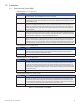
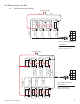
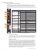
9.3.1 Detailed LED Descriptions
REG - CM Registration
Once a downstream channel has been negotiated between the CM and CMTS, the modem
attempts to register with the DHCP server and obtain the conguration le. This LED ashes
while the process takes place. Once the registration is complete, the LED will remain on solid.
This is the best indication that the IDH4 Series is communicating with the CMTS in the headend.
DS - Downstream Communication
This LED indicates the state of the CM's attempt to gain a downstream signal. This process may
take several seconds, depending on how long it takes the CM to locate a carrier signal and lock
onto a channel. The LED ashes while searching for the downstream DOCSIS channel and is on
solid when the downstream channel is locked.
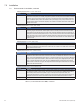
ACT - CPE Activity
The CPE activity LED ashes to indicate that data is being transmitted or received between the
IDH4 Series and a network device.
LNK - Network Communication Status
The Ethernet link LED remains ON when there is an active connection on the Ethernet port (e.g.,
a computer is connected for local diagnostics).
Rx/Tx Power
The Rx/Tx PWR LEDs provide the installer a quick verication of the modem transmit (Tx) and
receive (Rx) RF power levels. The Rx/Tx PWR LED will illuminate “green” when both the cable
modem Tx and cable modem Rx RF power levels are within the range as specied in the SCTE-
HMS PropertyTable. The LED indicator illuminates “blue” when Rx and/or Tx levels are within
the “warning” range as specied by the SCTE-HMS PropertyTable. The LED indicator illuminates
“red” when Rx and/or Tx levels are outside the range as specied by the SCTE-HMS Property-
Table.
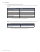
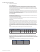
Refer to the following table for default ranges in the SCTE-HMS PropertyTable:
9.0 Start Up and Verification
Parameter alarm Enable HiHi Hi Lo LoLo Deadband
Rx
docsIfDownChannelPower
(OID:1.3.6.1.2.1.10.127.1.1.1.1.6)
00
(0F*)
150 100 -100 -150 15
Tx
docsIfCmStatusTxPower
(OID:1.3.6.1.2.1.10.127.1.2.2.1.3)
00
(0C*)
550 500 00 00 15
* Values in ( ) denote behavior of the Rx/TX LED if alarmEnable bits are set to ‘00’.
By default, alarmEnable is set to 00 (disabled) to prevent unwanted SNMP traps but the LED
behavior will function as if the alarmEnable were set to the values in the above table. If the alarm
Enable bits are set to anything other than 00 the LEDs will then follow the behavior of the desired
enable bit setting.
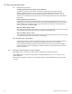
The above default values translate into the following Rx/Tx Power LED color ranges:
LED Color Rx Range (dBmV) Tx Range (dBmV)
Green +10 to -10 0 to +50
Blue +15 to +10 and -10 to -15 +50 to +55
Red >+15 and <-15 >+55