
Manual


6 746-257-B2-001, Rev. B (01/2014)
Figures
Fig. 1-1, AlphaNet IDH4X Series................................................................................................................................................................. 8
Fig. 1-2, AlphaNet IDH4L ............................................................................................................................................................................8
Fig. 1-3, Side view, AlphaNet IDH4 Series .................................................................................................................................................. 9
Fig. 2-1, Representative System Arrangement ......................................................................................................................................... 10
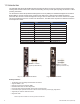
Fig. 3-1, Locations of MAC Address labels ............................................................................................................................................... 13
Fig. 3-2, Sample DOCSIS Conguration File ............................................................................................................................................ 16
Fig. 4-1, IDH4 Series Web Page ...............................................................................................................................................................19
Fig. 4-2, Local Area Connection Properties Screen .................................................................................................................................. 20
Fig. 4-3, Internet Protocol (TCP/IP) Properties Screen ............................................................................................................................. 20
Fig. 4-4, Local Area Connection Properties Screen, Windows 7 .............................................................................................................. 21
Fig. 4-5, Internet Protocol (TCP/IP) Properties Screen, Windows 7 ......................................................................................................... 21
Fig. 4-6, Web Server Home Page ............................................................................................................................................................. 22
Fig. 4-7, IDH4 Series Navigation Bar Items .............................................................................................................................................. 23
Fig. 4-9, Communication Parameters ....................................................................................................................................................... 24
Fig. 4-8, IDH4 Series Transponder Security Levels .................................................................................................................................. 24
Fig. 4-10, Communication Parameters ..................................................................................................................................................... 25
Fig. 4-11, Power Supply and Battery Parameters ..................................................................................................................................... 26
Fig. 4-13, Location of Start Button for Self Test ........................................................................................................................................ 27
Fig. 4-14, HMS Alarm Conguration ......................................................................................................................................................... 28
Fig. 4-15, Advanced I/O Controller Status Screen .................................................................................................................................... 29
Fig. 4-16, Advanced Power Supply Settings Screen ................................................................................................................................ 30
Fig. 4-18, Advanced Generator Status Screen ........................................................................................................................................ 31
Fig. 4-19, Event Log Screen ..................................................................................................................................................................... 32
Fig. 4-20, IDH4 Constellation Page........................................................................................................................................................... 33
Fig. 4-21, IDH4 Constellation Page........................................................................................................................................................... 34
Fig. 4-22, Sample QAM Constellation—Normal Centered Dots (Good Quality) ....................................................................................... 35
Fig. 4-23, Sample QAM Constellation—Fuzzy (Low CNR and/or Low MER) ........................................................................................... 35
Fig. 4-24, Sample QAM Constellation—"Doughnuts" (Coherent Interference) ......................................................................................... 36
Fig. 4-25, Sample QAM Constellation—Gaussian Noise .......................................................................................................................... 36
Fig. 4-26, Sample QAM Constellation—Circular Smear (Phase Noise) ................................................................................................... 37
Fig. 4-27, Sample QAM Constellation—Corners Squeezed to Center (Gain Compression) .................................................................... 37
Fig. 4-28, Sample QAM Constellation—Rectangular vs. Square (I-Q Imbalance).................................................................................... 38
Fig. 4-29, Sample QAM Constellation—Twisted or Skewed (Quadrature Distortion) ............................................................................... 38
Fig. 4-30, IDH4 Constellation Page........................................................................................................................................................... 39
Fig. 6-1, Sample Raw SNMP Alarm Trap .................................................................................................................................................. 46
Fig. 6-2, Sample Translated SNMP Alarm Trap ........................................................................................................................................ 46
Fig. 7-1, Removing the Inverter Module from the Power Supply ............................................................................................................. 53
Fig. 7-4, Connecting the Transponder to the Inverter Module................................................................................................................... 54
Fig. 7-2, The 18-pin jumper .......................................................................................................................................................................54
Fig. 7-3, The 18-pin jumper installed .........................................................................................................................................................54
Fig. 7-5, Removing the Inverter Module from the Power Supply ............................................................................................................. 55
Fig. 7-6, Removing the IDH4L sheet metal from the Inverter Module ....................................................................................................... 55
Fig. 7-7, The 18-pin jumper installed .........................................................................................................................................................56
Fig. 7-9, IDH4L attached to sheet metal ................................................................................................................................................... 56
Fig. 7-10, IDH4L / IM connection .............................................................................................................................................................. 56
Fig. 7-11, Completed assembly ................................................................................................................................................................. 56
Fig. 7-8, IDH4L 18-pin header ................................................................................................................................................................... 56
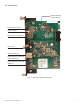
Fig. 7-12, IDH4X LEDs and Connectors ................................................................................................................................................... 57
Fig. 7-15, Connecting the RF Drop ........................................................................................................................................................... 59
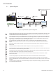
Fig. 7-16, System Interconnection Diagram .............................................................................................................................................. 59
Fig. 8-1, 36V System, Single String .......................................................................................................................................................... 64
Fig. 8-2, 36V System, Dual String ............................................................................................................................................................. 64
Fig. 8-3, 48V, Single String .......................................................................................................................................................................65
Fig.8-4, 48V, Dual String ...........................................................................................................................................................................65
Fig. 9-1, Initial Web Page ..........................................................................................................................................................................66
Fig. 9-2, HMS Tab Screen ......................................................................................................................................................................... 67
Fig. 9-3, LED Functionality and Indications............................................................................................................................................... 68
Fig. 11-1, Simplied Block Diagram Single IP Mode ................................................................................................................................. 76
Fig. 11-2, Simplied Block DiagramDual IP Mode ....................................................................................................................................76
Fig. 11-3, Single IP IDH4 Series Web Page .............................................................................................................................................. 77
Fig. 11-4, Dual IP IDH4 Series Web Page ................................................................................................................................................ 77
Fig. 11-5, Dual IP Conguration Settings for Transponder Web Server Communications Page .............................................................. 79
Fig. 11-6, Dual IP Parameters for Transponder Web Server General Page ............................................................................................. 79