
Manual

59
746-257-B2-001, Rev. B (01/2014)
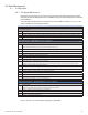
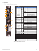
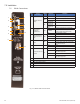
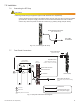
Fig. 7-16, System Interconnection Diagram
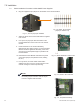
7.7 Front Panel Connections
Connections
Connections with more
than one power supply
Battery Sense Wire Harness
Refer to Section 8 for part numbers and wiring
options.
C
O
M
S
Y
S
C
O
M
S
Y
S
Generator (ECM)
ECM to SCM Interface
(Alpha P/N 704-709-20)
B
C
A
A
B
Comm Port
System Port
Battery Sense Connections
B
C
A
A
Environmental connection
Ethernet connection
RF connection
7.0 Installation
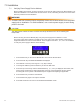
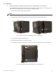
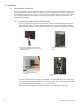
Connect the RF drop according to the diagram below. The RF drop must have a properly installed
ground block in the power supply enclosure. Recommended downstream RF level is 0 dBmV.
Connect any other front panel connections at this time (e.g. battery strings, tamper switch).
Install a grounded surge suppressor (Alpha P/N 162-028-10 or equivalent).
CAUTION!
RF Cable
to Headend
Grounded Surge Protector
(See Caution Above)
Fig. 7-15, Connecting the RF Drop
7.6 Connecting the RF Drop
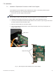
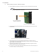
Linked CableUPS
Serial Interface Cards
IDH4X in
Primary XM2
AlphaBus Cable
(Alpha P/N 875-190-20 for 6',
-21 for 9', -22 for 18', -23 for 35')