AlphaNet IDH4 for XM2 and XM2-300HP Series DOCSIS® Status Monitor Technical Manual Effective: January, 2014
Power Alpha Technologies ®
AlphaNet IDH4 Series for XM2 and XM2-300HP DOCSIS® Status Monitor Technical Manual 745-257-B2-001, Rev. B Effective Date: January, 2014 Copyright 2014 Alpha Technologies, Inc. NOTE: Alpha denies responsibility for any damage or injury involving its enclosures, power supplies, generators, batteries or other hardware, manufactured by Alpha or members of the Alpha Group, when used for an unintended purpose, installed or operated in an unapproved manner, or improperly maintained.
Table of Contents Safety Notes........................................................................................................................................................................7 1.0 Introduction ...................................................................................................................................................................8 2.0 Overview......................................................................................................................
Contents 6.0 Data Management.......................................................................................................................................................42 6.1 SCTE-HMS MIBs ...........................................................................................................................................42 6.2 SCTE-HMS MIB Alarms.................................................................................................................................43 6.2.
Figures Fig. 1-1, AlphaNet IDH4X Series................................................................................................................................................................. 8 Fig. 1-2, AlphaNet IDH4L............................................................................................................................................................................. 8 Fig. 1-3, Side view, AlphaNet IDH4 Series....................................................................
Tables Table 2-1, LEDs and Indications.....................................................................................................................................................12 Table 3-1, Modem Community String Parameters..........................................................................................................................14 Table 3-2, Trap Destination Addresses....................................................................................................................
1.0 Introduction The AlphaNet IDH4 Series Embedded DOCSIS Transponder allows monitoring of Alpha power supplies through existing cable network infrastructure. Advanced networking services provide quick reporting and access to critical powering information. The IDH4 Series utilizes Simple Network Management Protocol (SNMP) and standard Management Information Bases (MIBs) to provide network status monitoring and diagnostics.
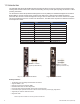
1.0 Introduction Intelligent CableUPS Interface (other side) Environmental IO Connector Tamper Connector Ethernet Port for Local Diagnostics RF Connector COM Port (IDH4X only) Battery Monitoring Connection A/B (IDH4 and IDH4X only) Battery Monitoring Connection C/D (IDH4X only) Fig. 1-3, Side view, AlphaNet IDH4 Series 746-257-B2-001, Rev.
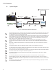
2.0 Overview 2.1 System Diagram 10 SNMP-based Network Management System 2 1 IDH4 Series Power Supply 5 4 3 External Generator Coax/HFC Network 6 7 CMTS TCP/IP Network Local Computer 7 DHCP Server 8 TFTP Server 9 TOD Server 11 Web Browser Fig. 2-1, Representative System Arrangement 10 1 All power supply data is stored in the power supply inverter module's class information base (CIB) tables in the power supply.
2.0 Overview 2.2 Network Connectivity The IDH4 Series cable modem must be recognized by the CMTS as a valid device to be assigned an IP address from the DHCP server, to locate the TFTP and TOD servers and to communicate with the SNMP management server (trap receiver). Data from both the cable modem and power supply are accessed and managed through the modem’s IP address on the secure private modem network. The transponder is not accessible from the public Customer Premises Equipment (CPE) network.
2.0 Overview IDH4 Series Start-up and Reboot Routine TCP/IP Network 2.4 TFTP Server 5 Network Management System TOD Server 4 MIB Browser DHCP Server 3 Web Browser Routers Switches Firewalls HFC Network CMTS 2 6 IDH4 Series 1 Power Supply 7 Local Laptop The above diagram, read left to right, indicates the order of operations as the transponder comes online. There are certain conditions that must exist for each step to occur, resulting in successful data monitoring and management.
3.0 Network Configuration 3.1 Provisioning the DHCP Server with the MAC addresses On the DHCP server, assign the cable modem’s RF MAC address with a DOCSIS Configuration File to set modem communication options. (See Section 3.2 for instructions on how to create a DOCSIS Configuration File). The RF and CPE MAC addresses are located in two places on the IDH4 Series and on the packing slip, see below. Cable Modem and CPE MAC address label Identifier label Fig.
3.0 Network Configuration 3.2 The DOCSIS Configuration File A cable modem’s DOCSIS Configuration File is a type-length-value (TLV) file that contains important operational parameters as defined by the DOCSIS standards. It provides certain settings for the cable modem. In addition to standard entries, settings in the DOCSIS Configuration File should include the modem’s community strings and, if an upgrade is necessary, firmware upgrade parameters. Place the configuration file in the TFTP root directory.
3.0 Network Configuration 3.2 The DOCSIS Configuration File 3.2.2 Setting SNMP Trap Destination Addresses Set the SNMP Trap Destination addresses via the DOCSIS Configuration File by including the following SNMP parameters: MIB Parameter Object ID Description Value docsDevNmAccessIP 1.3.6.1.2.1.69.1.2.1.2.X IP address of trap destination, e.g. NMS server e.g. 10.20.30.40 docsDevNmAccessIpMask 1.3.6.1.2.1.69.1.2.1.3.X Must be set to 255.255.255.255 per RFC 4639 255.255.255.
3.0 Network Configuration 3.2 The DOCSIS Configuration File 3.2.3 Sample DOCSIS Configuration File Entries A SNMP MIB Object (11) [Len=21]:docsDevNmAccessStatus.1/4 SNMP MIB Object (11) [Len=21]:docsDevNmAccesslp.1/10.56.21.0 SNMP MIB Object (11) [Len=21]:docsDevNmAccesslpMask.1/255.255.255.0 SNMP MIB Object (11) [Len=25]:docsDevNmAccessCommunity.1/"RW STRING" SNMP MIB Object (11) [Len=25]:docsDevNmAccessInterfaces.1/"@" SNMP MIB Object (11) [Len=21]:docsDevNmAccessControl.
3.0 Network Configuration 3.2 The DOCSIS Configuration File 3.2.4 Proprietary Configuration File ‘idhdoc04.cfg’ The IDH4 Series will attempt to download a TLV-formatted file ‘idhdoc04.cfg’ from the modem’s provisioning TFTP server at start up and every 24 hours thereafter. The idhdoc04.cfg proprietary configuration file is optional and provides an alternative method to the modem’s DOCSIS configuration file for deploying Alpha proprietary SNMP MIB parameters to field-installed IDH4 Series transponders.
3.0 Network Configuration 3.3 Setting Communication Options Communications Settings may be changed through the Alpha MIB remotely using an SNMP MIB browser or automatically by placing the SNMP parameters into the DOCSIS config file. See Section 6, Data Management for an explanation of the Alpha MIB. NOTE: Before setting options, verify UDP ports 37, 69, 161, 162 and TCP port 80 are not blocked. SNMP Parameter Type Description Value atiMgmtSnmpTrapOnNormal OID: 1.3.6.1.4.1.926.1.3.1.5.1.
4.0 Web Interface Overview The IDH4 Series power supply transponder provides an embedded Web server interface to allow operations personnel the ability to connect locally or remotely via TCP/IP over Ethernet with a laptop/ computer to verify the status of common data points and to configure various operating parameters. 4.
4.0 Web Interface 4.1 Local Web Server Access NOTE: If you are unable to view the home page of the IDH4 Series using IP Address 192.168.100.1, the network configuration on the computer that is being used to connect to the IDH4 Series transponder may require a temporary static IP address to be configured. Use the following procedure to configure a static IP address on a laptop or computer for Windows XP: 1. Click on the Start button (lower left button on most Windows® computers). 2.
4.0 Web Interface 4.1 Local Web Server Access Use the following procedure to configure a static IP address on a laptop or computer with the Windows 7 operating system: 1. Click the Start button (lower left button on most Windows® computers). 2. When the window pops up, click Control Panel (usually about half the way down the second column). 3. Click Network and Sharing Center. 4. Click Local Area Connection. 5. Click the Properties button. 6. You will see a dialog box much like Fig.
4.0 Web Interface 4.2 Remote Web Server Access To remotely access the IDH4 Series transponder Web server utilizing a Web browser, follow the procedure outlined below: NOTE: For Web server (HTTP) access, port 80 must not be blocked. 1. Connect the laptop or computer’s network interface port to the company’s Ethernet network. 2. Open a Web browser. 3. Enter the IDH4 Series' designated IP address (e.g., 192.168.1.124) into the Web browser’s address field. 4.
4.0 Web Interface 4.3 Navigating the Web Page Once the Web page has been successfully accessed, the operator is able to select a link on the header bar and the page specific to the topic will open enabling real-time data to be observed. See Fig. 4-7 for IDH4 Series navigation bar items. Commonly used parameters for quick diagnostics of Power Supply, Communications, Batteries and Generator.
4.0 Web Interface 4.3 Navigating the Web Page 4.3.1 Web Interface Security Levels Within the IDH4 Series transponder are two levels of function-specific security. General operations are set at Level 1 and configuration-related functions are set at Level 2. Default User ID and Passwords are shown in the figure below. IDH4 Series Web Page Security OID Function Value 1.3.6.1.4.1.4413.2.2.2.1.1.3.3.0 Level 1 User Name Alpha 1.3.6.1.4.1.4413.2.2.2.1.1.3.4.0 Level 1 Security Password AlphaGet 1.3.6.1.4.
4.0 Web Interface 4.4 Verifying Communication Parameters Fig. 4-10, Communication Parameters (data values shown for illustration purposes only) 746-257-B2-001, Rev.
4.0 Web Interface 4.5 Verifying Power Supply and Battery Parameters The General tab of the Web page also displays the common power supply and battery parameter values. Important parameters such as current alarm status, inverter status and tamper status can be quickly verified on this page. Additional power supply parameters can be viewed and edited on the Power Supply page located in the Advanced Configuration menu. Fig.
4.0 Web Interface 4.6 Remote Self Tests via the Web Page Remote Self Tests on power supplies may be started and stopped via the IDH4 Series Web page. This requires a Level 1 login. Refer to Section 4.3.1, Web Interface Security Levels for User Name and Security Password. To launch a remote Self Test, click on the Start Test button. To stop a remote Self Test before the predefined test duration, click on the Stop Test button. Fig.
4.0 Web Interface 4.7 Viewing HMS Alarm Status via the Web Page HMS alarm levels and currently reported states may be viewed by clicking on the HMS Alarms link on the Advanced Configuration menu. An example is shown below. Parameter values cannot be edited on this Web page. An SNMP MIB browser or status monitoring software may be used for such edits. Refer to Table 6-3, Recommended Settings for IDH4 Series Analog Alarms for information regarding the scaling applied to the indicated values. Fig.
4.0 Web Interface 4.8 Setting the I/O Controller via the Web Page Settings for the Tamper Switch and I/O Controller may be made by accessing the the I/O - Environment page from the Advanced Configuration drop down list. The Tamper Switch polarity may be changed by clicking on the preferred Tamper Switch polarity button. The I/O Controller section provides a user interface to select the type of device that will be connected and monitored via the ENV connector of the transponder.
4.0 Web Interface 4.9 Viewing Power Supply Settings via the Web Page Connected power supply parameters may be viewed by clicking on the Advanced Configuration heading, and selecting Power Supplies from the drop down list. Power supply Self Tests may be remotely started by clicking on the Start Test button. When prompted, refer to Section 4.3.1, Web Interface Security Levels for the applicable User Name and Password. Fig.
4.0 Web Interface 4.10 Viewing and Configuring Generator Settings via the Web Page When a generator is connected to an IDH4X, the generator page listed in the Advanced Configuration menu will populate a list of the various parameters and alarm statuses. Generator Self Tests may be remotely started by clicking on the Start Test button. When prompted, refer to Section 4.3.1, Web Interface Security Levels for User Name and Security Password. Fig.
4.0 Web Interface 4.11 Viewing the Modem Event Log via the Web Page The transponder's modem event log may be viewed using a Web browser. From the General ("home") page, click on the History link, and select Cable Modem Log from the drop down list. The Cable Modem Log displays the contents of the docsDevEventTable in an easy to read format.
4.0 Web Interface 4.12 QAM Constellation Select the Tools menu to access the Constellation page. Click the Constellation menu item to view the Constellation display for the DOCSIS channel. The page will automatically refresh until the updates remaining counter reaches 0. Clicking the Run button restarts the automatic refresh, and clicking the Stop button stops it. Fig. 4-20, IDH4 Constellation Page (data values shown for illustration purposes only) 4.
4.0 Web Interface 4.0 4.0 Web Web Interface Interface 4.13 Interpreting QAM Constellation Data by Visual Inspection 4.15 4.15 Interpreting Interpreting QAM QAM Constellation Constellation Data Data by Visual Inspection The usefulness of the QAM constellation comes in the ability to recognize common shapes and configurations within the map.
4.0 4.0 Web Web Interface Interface 4.0 4.0 Web Web Interface Interface 4.13 4.13 Interpreting InterpretingQAM QAMConstellation ConstellationData Databy byVisual VisualInspection, Inspection,continued continued 4.0 Web Web Interface Interface 4.0 4.13 4.13 Interpreting InterpretingQAM QAMConstellation ConstellationData Databy byVisual VisualInspection, Inspection,continued continued 4.16 Interpreting InterpretingQAM QAMConstellation ConstellationData Databy byVisual VisualInspection Inspection 4.16 Fig.
4.0 Web Interface 4.0 Web Interface 4.13 Interpreting QAM Constellation Data by Visual Inspection, continued 4.0 Web Interface 4.16 4.13 Interpreting QAM Constellation Data byInspection Visual Inspection, continued Interpreting QAM Constellation Data by Visual Fig. 4-17, Sample QAM Constellation—"Doughnuts" (Coherent Interference) Fig. 4-17, Sample QAM Constellation—"Doughnuts" (Coherent Interference) Constellation—"Doughnuts" (Coherent (Coherent Interference) Interference) Fig.
4.0 4.0 Web Web Interface Interface 4.0Web WebInterface Interface 4.0 4.13 Interpreting QAM Constellation Data by Visual Inspection, continued 4.13 Interpreting QAM Constellation by Visual Inspection, continued 4.13 Interpreting QAM Constellation Data by Visual Inspection, continued 4.16 Interpreting QAM ConstellationData Data by Visual Inspection 4.16 Data by Visual Inspection 4.13 Interpreting InterpretingQAM QAMConstellation Constellation Data by Visual Inspection, continued Fig.
4.0 Web Interface 4.0 Web Interface 4.0 Web Interface 4.13 Interpreting InterpretingQAM QAM Constellation Constellation Data byby Visual Inspection, continued 4.16 Data Visual Inspection 4.13 Interpreting QAM Constellation Data by Visual Inspection, continued Fig. 4-21, Sample QAM Constellation—Rectangular vs. Square (I-Q Imbalance) 4-28, Sample QAM Constellation—Rectangular vs. Square Imbalance) Fig. Fig. 4-21, Sample QAM Constellation—Rectangular vs. Square (I-Q (I-Q Imbalance) Fig.
4.0 Web Interface 4.17 Microreflections Select the Tools menu to access the Microreflections page. The CMTS Adaptive equalization must be enabled for the active upstream channel for this page to display valid data. The Microreflections page provides information about impairments on the line and the approximate distance(s) of those impairment(s). Placing the mouse pointer over each bar provides details about that particular reading. Fig.
5.0 Upgrading Firmware 5.1 Upgrading IDH4 Series Modem Firmware The firmware is upgraded using standard DOCSIS methods as defined in RFC4639. There are two ways to upgrade the modem’s firmware: by directly setting the appropriate MIB parameters in the docsDevSoftware branch, or by including the appropriate SNMP parameters and values in the modem’s DOCSIS Configuration File, stored on the TFTP root directory. Both methods are explained below. 5.1.
5.0 Upgrading Firmware 5.1.3 Upgrading Manually by Setting SNMP Parameters 1. Acquire the firmware and CVC files for your IDH4 Series from Alpha Technologies. 2. Import the CVC into the modem’s DOCSIS Configuration File (to create a Configuration File, see Section 3.2). 3. Set the following MIB parameters using an SNMP MIB browser. For additional information regarding the SNMP MIB parameters, refer to the table in Section 5.1.2., "Modem Firmware Upgrade SNMP Parameters".
6.0 Data Management 6.1 SCTE-HMS MIBs The IDH4 Series remotely reports power supply data and alarms using the Simple Network Management Protocol (SNMP) over the DOCSIS (Data Over Cable Service Interface Specification) communications standard. The IDH4 Series typically reports into a centralized Network Management System (NMS) through a standard collection of data access points referred to as the SCTE-HMS Management Information Bases (MIBs).
6.0 Data Management 6.2 SCTE-HMS MIB Alarms 6.2.1 SCTE-HMS Configurable Alarms The HMS discrete and analog alarms provide the capability to monitor and alarm various power supply and environmental conditions and measurements. The alarms in the SCTEHMS propertyTable and the discretePropertyTable can be defined and set to provide a custom monitoring system. The following section provides an example and detailed information on how to set values, enable or disable alarms in the MIB tables.
6.0 Data Management 6.2.1 SCTE-HMS Configurable Alarms The following table displays the various XM2 Series analog alarms with common settings for the IDH4 Series Transponder.
6.0 Data Management 6.2.
6.0 Data Management 6.2.2 SNMP Traps Use of SNMP Traps allow the network manager to set conditions (alarms) under which the device (or devices) autonomously report to the headend the existence of the pre-configured event. The type of event determines the level of action to be taken. 1. Verify the IP address of the trap destination server(s) has been configured. If the trap destination server requires configuration, refer to Section 3.2.
6.0 Data Management 6.2.2 SNMP Alarm Traps Varbind Explanation Binding #1 commonPhysAddress OID: 1.3.6.1.4.1.5591.1.3.2.7.0 MAC Address of the transponder Binding #2 commonLogicalID OID: 1.3.6.1.4.1.5591.1.3.1.1.0 Optional user-configurable parameter that is often used to provide a unique logical name, or even the physical address of where the transponder is installed. Binding #3 alarmLogInformation OID: 1.3.6.1.4.1.5591.1.2.3.1.2.
6.0 Data Management 6.2.3 General Power Supply Alarms General power supply alarms are passed directly from the power supply to the transponder without specific definition and are classified in the HMS MIB table as psMinorAlarm and psMajorAlarm. There are a number of problems that can generate these alarms and the exact nature of the situation is not specified.
6.0 Data Management 6.3 The Alpha MIBs The below MIB files are backward-compatible with the existing Alpha Technologies IDH4 series transponders. These MIBs are available by contacting Alpha Technical Support or from the Alpha website. A complete listing is shown below: ATI-BB-SYS-APPS-MIB.my ATI-BB-SYS-LOGS-MIB.my ATI-BB-SYS-VIEW-MIB.my ATI-MANAGEMENT-MIB.my ATI-MGMT-SNMP-MIB.my ATI-MGMT-SYS-ACCESS-MIB.my ATI-MGMT-SYS-DOWNLOAD-MIB.my ATI-MGMT-SYS-GENRL-CTRL-MIB.my ATI-MGMT-SYS-GENRL-INFO-MIB.
6.0 Data Management 6.3 The Alpha MIBs The Alpha MIB is defined within the enterprises branch of the MIB tree starting at 1.3.6.1.4.1.926 and is organized as shown in the overview below: MIB Tree ccit iso (1) org (1.3) dod (1.3.6) internet (1.3.6.1) directory (1.3.6.1.1) mgmt (1.3.6.1.2) experimental (1.3.6.1.3) private (1.3.6.1.4) enterprises (1.3.6.1.4.1) atl(1.3.6.1.4.1.926) alphaTechInc(1.3.6.1.4.1.926.1) atiLegacyReserved01(1.3.6.1.4.1.926.1.1) atiTables (1.3.6.1.4.1.926.1.2) atiManagement (1.3.6.1.
6.0 Data Management 6.3 The Alpha MIBs 6.3.1 The Alpha MIB Structure Measurements and settings for the power supply, generator, batteries and IDH4 are accessed using Simple Network Management Protocol (SNMP) through the Alpha Management Information Base (MIB) files. The Alpha MIB is defined within the enterprise branch of the MIB tree starting at 1.3.6.1.4.1.926 and is organized into the following branches: Alpha CIB Tables – atiTables (1.3.6.1.4.1.926.1.2.
7.0 Installation 7.1 Verifying Power Supply Device Address Before installing the hardware, provision the DHCP server with the cable modem’s RF MAC Address. This allows the installation to be verified while the technician is on-site, eliminating the need for a second visit if there are problems with the installation. WARNING! To reduce the risk of electric shock, completely remove the Inverter Module from the power supply prior to installation.
7.0 Installation 7.2 Installation / Replacement Procedure in XM2 Power Supplies If the CableUPS has been shipped without a IDH4 Series module, or the existing module requires removal and replacement, do so via the the following procedure: 1. Switch OFF the power supply’s battery breaker. NOTE: With the battery breaker in the OFF position, the power supply will not go into inverter mode. 2. Unplug all Inverter Module connections (e.g. battery cable, remote temperature sensor). 3.
7.0 Installation 7.2 Module Installation Procedure in XM2 Power Supplies 6. Plug the supplied 18-pin jumper into the header on the back of the IDH4 Series circuit board. NOTE: To prevent damage to the IDH4, do not reuse the existing 18-pin connector. Instead, use the jumper supplied with the transponder. Fig. 7-2, The 18-pin jumper (Alpha p/n 540-286-19) Fig. 7-3, The 18-pin jumper installed 7. Line up the 18-pin jumper with the header on the Inverter Module and connect the unit to the Inverter Module.
7.0 Installation 7.3 IDH4L Installation / Replacement Procedure in XM2-300HP Power Supplies If the XM2-300HP High-Efficiency CableUPS has been shipped without a IDH4L, or the existing module requires removal and replacement, do so via the the following procedure: 1. Switch OFF the power supply’s battery breaker. NOTE: With the battery breaker in the OFF position, the power supply will not go into inverter mode. 2. Unplug all Inverter Module connections (e.g. battery cable, remote temperature sensor).
7.0 Installation 7.3 IDH4L Installation Procedure in XM2-300HP Power Supplies 6. Plug the supplied 18-pin jumper into the header on the Inverter Module. 6 Fig. 7-8, IDH4L 18-pin header (Alpha p/n 540-581-19) Fig. 7-7, The 18-pin jumper installed 7. Attach the IDH4L to the sheet metal with the supplied 6-32 screws. 8. Line up the 18-pin jumper with the header on the Inverter Module and connect the unit to the inverter module. 9. Fasten the IDH4L to the Inverter Module by tightening the two captive screws.
7.0 Installation 7.
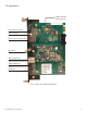
7.0 Installation 7.5 IDH4L Connections Item 1 LED or Connector N/A 7 2 GRN 1 ALM/RDY: Alarm and Ready RED 8 3 4 9 2 10 5 3 6 11 Status REG: Upstream ranging and registration lock GRN DS: Downstream RF Carrier detection and lock.
7.0 Installation 7.6 Connecting the RF Drop CAUTION! Install a grounded surge suppressor (Alpha P/N 162-028-10 or equivalent). Connect the RF drop according to the diagram below. The RF drop must have a properly installed ground block in the power supply enclosure. Recommended downstream RF level is 0 dBmV. Connect any other front panel connections at this time (e.g. battery strings, tamper switch). Grounded Surge Protector (See Caution Above) RF Cable to Headend Fig. 7-15, Connecting the RF Drop 7.
7.0 Installation 7.8 Environmental Connections The IDH4X and IDH4L have the capability to monitor and control enclosure environmental heating and cooling. Typically this is used for battery mat heaters in cold environments, however the functionality may be implemented to control enclosure fans or air conditioners. The following section will outline the details of the controls available and will include an example of a typical battery heater mat configuration and explanation of the settings. 7.8.
7.0 Installation 7.9 Environmental Control MIBs atiMgmtSysTempCtrl (1.3.6.1.4.1.926.1.3.2.4.1) Value list Description off(1) Temperature device is off. This setting is non-volatile, if the variable is in this state upon reset (or power-up) this value will be retained. This is the DEFAULT factory value for this variable. onTimer(2) Temperature device is turned on for a predefined time.
7.0 Installation 7.9 Environmental Control MIBs, continued atiMgmtSysTempTemperature (1.3.6.1.4.1.926.1.3.2.4.5) Size list Description 1...70 Thermostatic temperature setpoint in degrees centigrade. When this device is set to control the temperature device based on temperature, this variable (along with the hysteresis variable) will be used to determine when the temperature device is to be turned on and off. This value is compared to the value from the battery temperature sensor.
7.0 Installation 7.10 Configuring the Battery Heater Mat Controller In this example, values are written to their respective OIDs to set temperatures, control mode and status reporting: Set these OIDs to the specified value Functionality atiMgmtSysTempTemperature (1.3.6.1.4.1.926.1.3.2.4.5) to 5 Heater turns on at 5°C atiMgmtSysTempHysteresis (1.3.6.1.4.1.926.1.3.2.4.6) to 3 3°C of permitted controller overshoot (in this case, would turn off at 8°C) atiMgmtSysTempCtrl (1.3.6.1.4.1.926.1.3.2.4.
8.0 Battery Sense Wire Kits 8.1 36V Single and Dual Strings To Power Supply Black Fig. 8-1, 36V System, Single String NEG (-) 3A 2A 1A POS (+) POS (+) POS (+) Vbatt 2A [C] 24V Pin 3 Sense Wire Kits: Alpha P/N: 874-842-21 (6') Alpha P/N: 874-842-27 (9') A/B [C/D] NEG Pin 1 NEG (-) Vbatt 1A [C] 12V Pin 2 NEG (-) Vbatt 3A [C] 36V Pin 4 Red 4 8 3 7 2 6 1 5 Back of Plug To Power Supply Red Black Fig.
8.0 Battery Sense Wire Kits 8.2 48V Single and Dual Strings To Power Supply Red 3A 4A 1A POS Vbatt 3A [C] 36V Pin 4 A/B [C/D] NEG Pin 1 NEG 2A POS Vbatt 4A [C/D] 48V Pin 8 POS NEG POS Vbatt 1A [C] 12V Pin 2 NEG Vbatt 2A [C] 24V Pin 3 NEG Black 5 1 6 2 7 3 8 4 Back of Plug Fig. 8-3, 48V, Single String Sense Wire Kits: Alpha P/N: 874-841-21 (6') Alpha P/N: 874-841-25 (9') To Power Supply 4B POS(+) 746-257-B2-001, Rev.
9.0 Start Up and Verification 9.1 Initial Startup and Local Verification To confirm successful hardware installation before leaving the installation site, verify network connectivity and correct hardware interconnection. 9.1.1 To Verify Network Connectivity: The DS and REG LEDs on the front of the IDH4 Series should be ON solid green. This indicates successful registration with the headend.
9.0 Start Up and Verification 9.2 Verifying Correct Hardware Interconnection The BAT A/B and BAT C/D LED indicators on the front panel of the IDH4 Series unit should illuminate solid green once the battery wiring harnesses are correctly installed. NOTE: The IDH4X model provides both BAT A/B and BAT C/D LED indicators and battery harness connectors (supports a maximum 4 battery strings).
9.0 Start Up and Verification 9.3 System Status Indicators and Reset button As viewed from the front of the unit, the IDH4 Series utilizes light emitting diodes (LEDs) to indicate system status. During system startup, the LEDs will first blink momentarily then indicate the current status of a variety of parameters on the IDH4 Series transponder. The LEDs indicate alarms, RF power level status, battery string connectivity and communications activity with the network. A description of each LED follows.
9.0 Start Up and Verification 9.3.1 Detailed LED Descriptions REG - CM Registration Once a downstream channel has been negotiated between the CM and CMTS, the modem attempts to register with the DHCP server and obtain the configuration file. This LED flashes while the process takes place. Once the registration is complete, the LED will remain on solid. This is the best indication that the IDH4 Series is communicating with the CMTS in the headend.
9.0 Start Up and Verification 9.3.1 Detailed LED Descriptions Configuring the Rx/Tx Power LED - Custom Settings If desired, the RF Power Level ranges for the Rx/Tx PWR LED may be customized via SNMP by adjusting the HiHi, Hi, Lo, LoLo values for the docsIfDownChannelPower and docsIfCmStatusTxPower in the SCTE-HMS Property Table (OID:1.3.6.1.4.1.5591.1.1.1). Be careful not to exceed the Input Level and Output Power range specifications of the IDH4 Series transponder.
10.0 Alpha MIB Parameters 10.1 Definitions and Settings The following tables display commonly-configured Alpha MIB parameters and provide specific information with regard to functionality, options, OIDs, types and variables. NOTE: The Alpha MIB Definitions and Settings are subject to change without notice and should only be used for advanced diagnostics. The SCTE-HMS MIBs listed in Section 6 should be implemented for status monitoring & control. Parameter OID atiMgntSnmp 1.3.6.1.4.1.926.1.3.1.
10.0 Alpha MIB Parameters 10.1 Definitions and Settings Parameter OID Description Access Type Value COMMUNITY STRINGS atiMgntSnmpCommunities 1.3.6.1.4.1.926.1.3.1.4.0 Object Identifier atiMgmtSnmpCommGet 1.3.6.1.4.1.926.1.3.1.4.1.0 Default "Read" Community String Read/Write Octet String AlphaGet (default atiMgmtSnmpCommSet 1.3.6.1.4.1.926.1.3.1.4.2.0 Default "Read/Write" Community String Read/Write Octet String AlphaSet (default) SNMP TRAP atiMgmtSnmpControls 1.3.6.1.4.1.926.1.3.1.
10.0 Alpha MIB Parameters 10.1 Definitions and Settings Parameter OID Description Access Type Value 1.3.6.1.4.1.926.1.3.2.6.1.0 Determines when tamper is active Read/Write 1=doorOpenWhenContactOpen GENERAL CONTROLS atiMgmtSysTamperPolarity Integer 2=doorOpenWhenContactClosed (default) atiMgmtSysAlphaBusSize 1.3.6.1.4.1.926.1.3.2.6.2.0 Internal microprocessor communications bus size. Alpha XM2 series power supplies use 9 bit.
10.0 Alpha MIB Parameters 10.1 Definitions and Settings Parameter OID Description Access Type Value SYSTEM ALARMS atiBBSysViewAlarms 1.3.6.1.4.1.926.1.4.1.1.2 Object Identifier atiBBSysViewMajorAlarm 1.3.6.1.4.1.926.1.4.1.1.2.1.0 Indicates if any of the items monitored are in a major alarm state. Read Only Integer 1=OK 2=Alarm atiBBSysViewMinorAlarm 1.3.6.1.4.1.926.1.4.1.1.2.2.0 Indicates if any of the items monitored are in a minor alarm state.
10.0 Alpha MIB Parameters 10.1 Definitions and Settings Broadcom MIBS: Parameter OID Description Access Type Value HTTP Management MIB httpMgmt 1.3.6.1.4.1.4413.2.2.2.1.1.3 httpAdminId 1.3.6.1.4.1.4413.2.2.2.1.1.3.1.0 Controls and reflects the user name for admin level HTTP priveleges. Read/Write Octet String Alpha (Default) httpAdminPassword 1.3.6.1.4.1.4413.2.2.2.1.1.3.2.0 Controls and reflects the password for admin level HTTP priveleges.
11.0 Dual IP Mode 11.1 Overview The IDH4 Series can operate in either Single (default) or Dual IP mode. In Single IP mode, data from both the cable modem and power supply are accessed and managed through the modem’s IP address on the secure private modem network. In Dual IP mode, the Communications Module acts like a CPE device to the cable modem and registers a second IP address on the public CPE network.
11.0 Dual IP Mode 11.2 Web Comparison, Single IP Mode/Dual IP Mode To easily determine the configuration of the Communications Module when viewing it on its web page, check the Configuration line as well as the entries for the CM and CPE addresses. A single IP Communications Module will display a CM MAC address only, while a Dual IP Communications Module will also indicate a CPE address. Displays CM MAC address only Fig.
11.0 Dual IP Mode 11.3 Configuring Dual IP Mode To switch the IDH4 Series Communications Module from Single to Dual IP mode the atiMgmtSnmpSnmpCPEAccess parameter of the Alpha MIB will need to be enabled. The Dual IP enable setting can be set through the DOCSIS Configuration File, the IDH4 Setup File (atidoc03.cfg), the Provisioning Mode via the Communications Web page or remotely using SNMP by setting the following Alpha MIB: MIB Parameter Object ID Description Value atiMgmtSnmpSnmpCPEAccess 1.3.6.1.
11.0 Dual IP Mode 11.3 Configuring Dual IP Mode, continued To change the CPE IP address allocation option from DHCP to Static via the Web Server, refer to the following: 1. Connect to IDH4 via Web browser per the procedure in Section 4.0, Web Interface. 2. In the Advanced Configuration menu of the Transponder Web page, click the Communications button. 3. Click the Static button in the CPE Communications Module column of the page. Refer to Figure 115.
11.0 Dual IP Mode 11.3 Configuring Dual IP Mode, continued 11.3.1 atidoc03.cfg in Dual IP Mode NOTE: Refer to Section 3.3.5 for details on using the atidoc03.cfg file to propagate custom settings to field-deployed IDH4x or IDH4L Communications Modules. In Dual IP mode, the Transponder will first attempt to download the proprietary configuration file atidoc03.cfg through the CPE’s interface from a TFTP server on the CPE network.
11.0 Dual IP Mode 11.3 Configuring Dual IP Mode, continued 11.3.3 Specifying atidoc03.cfg name and location via DHCP Tags In the User-defined area of the DHCP Tags, above option 192, the Communications Module will look for the following value: Tag: [Insert Unique Tag Name, e.g. ‘ati-tag’] Value: aticonfig In the Tag value immediately following will be the value for the TFTP server to use: Tag: [Insert Unique Tag Name, e.g. ‘ati-ip’] Value: IP address of TFTP server (i.e. 192.168.1.
11.0 Dual IP Mode 11.4 Dual IP SNMP Community Strings The Communications Module community strings used for the CPE Communications Module in Dual IP mode can be configured by the operator. The default Communications Module read-only community string is AlphaGet. The default read-write community string is AlphaSet. These settings can be configured with the DOCSIS Configuration File, the IDH4 Setup File (aitdoc03.
12.
12.
13.
Alpha Technologies Inc. 3767 Alpha Way Bellingham, WA 98226 United States Tel: +1 360 647 2360 Fax: +1 360 671 4936 Alpha Technologies Europe Ltd. Twyford House Thorley Bishop’s Stortford Hertfordshire, CM22 7PA United Kingdom Tel: +44 1279 501110 Fax: +44 1279 659870 Alpha Technologies Suite 1903, Tower 1 33 Canton Road, Kowloon Hong Kong, China Phone: +852 2736 8663 Fax: +852 2199 7988 Alpha Technologies Ltd.