
Instruction Manual


9745-814-B0-001, Rev. A
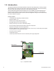
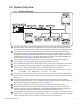
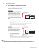
2.0 System Overview
2.1 System Diagram
All power supply, battery, and generator data are stored in the class information base (CIB) tables in
the power supply. These data are accessible directly via the power supply’s smart display (see the
power supply’s technical manual for details). The CIB tables are the source of the transponder’s data.
The XP-DSM is comprised of a cable modem and a transponder. The transponder contains both
SCTE-HMS management Information base (MIBs) and the propriety Alpha MIB tables. The SCTE-
HMS MIBs are industry standard MIB tables that store power supply, battery, and generator data from
the CIB tables (see Section 6.1). The Alpha MIB contains all the data of the SCTE-HMS MIBs plus
additional power supply settings and values, and transponder data.
Power supply and transponder parameters can be monitored and set locally using a personal
computer and a Local Port Adapter (Alpha P/N 745-826-21) (see Section 4.0).
The XP-DSM transmits data via its cable modem directly over the Coax or Hybrid ber-coax network.
The Cable Modem Termination System (CMTS) is the bridge between the cable network and the
TCP/IP network. The XP-DSM’s cable modem communicates directly with the CMTS.
The following ports of the Transmission Control Protocol/Internet Protocol network must be opened:
161 = SNMP 162 = SNMP Traps 69 = TFTP 80 = HTTP
The Dynamic Host Conguration (DHCP) server needs to be provisioned with the XP-DSM’s cable
modem RF MAC Address: the MAC Address needs to be assigned a DOCSIS Conguration File (see
Section 3.1).
The DOCSIS Conguration File should be saved in the TFTP Root Directory of the Trivial File
Transfer Protocol (TFTP) Server. If used, a DSM Setup File should be placed in the same location. To
build DOCSIS Conguration or DSM Setup Files, see Section 3.0.
The Time of Day (TOD) Server provides the cable modem with the current date and time.
A Network Management System (NMS) or MIB Browser allows remote monitoring of parameter
values and changing of settings in MIB tables. SCTE-HMS and Alpha MIBs must be installed in the
browser (Section 6.0). Alarms and traps can be set and monitored (see Section 6.3).
In both Single and Dual IP Modes, power supply parameters can be monitored on an internal network
Web browser. In Dual IP Mode only, the transponder is given an IP address independent of the cable
modem and parameters can be monitored on the public network (see Section 2.2).
1
2
3
4
5
6
8
7
9
10
OUTPUT2
OUTPUT1ALRI
Battery
Input
Temp
Probe
Battery
Breaker
OUTPUT1B
N+1
N+1
ALM
RDY
COM
LNK
RF
REG
DS
TMPR
CTRL
C
O
M
E
T
H
C
D
A
B
L
O
C
A
L
2
XP-DSM
1
Power Supply
3
Local Computer
4
Coax/HFC Network
5
CMTS
6
TCP/IP Network
11
Web Browser
10
MIB Browser
7
DHCP Server
8
TFTP Server
9
TOD Server
11