
Instruction Manual

61745-814-B0-001, Rev. A
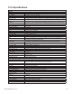
12.0Specications
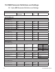
XP-DSMDOCSISStatusMonitorSpecications
Interface
Power Supplies Supported XM2, XM2VP, GMX
RF Connection F-connector, female, 75 ohm
LED Indicators Alarm, Ready, Comm, Link, DS, REG
XM2 Data and Power Interface 18-pin DIL header, proprietary
Tamper 2 pin header
Battery Input A/B 8 pin, female connector, string A and B, 36V or 48V voltage monitoring. Congurable to monitor up
to 6 x 6V batteries
Multi-Device Communications RJ-12 offset, RS-485 multidrop, communication for three XM2s and an AlphaGen
Local Port RJ-12, RS-232, 19.2,N,8,1 Requires serial port adaptor for laptop connection. Access to power
supply MIB data and network parameters
Electrical/Mechanical/Environmental
Operating Temperature -40ºC to +65ºC
Storage Temperature -40ºC to +85ºC
Humidity 10-90% non-condensing
Emissions EN50022 Class A1, FCC Part 15 Class A1, one Installed in XM2 power supply
Surge IEEE C62.41-1991, cat B3, 6KV
Warranty 2 years
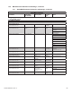
Network Communications
Network Protocols IP, UDP, TCP, DHCP, TFTP
SNMP v1, v2c
Embedded Web Interface “Read access MIB variables, Read-Write access networking parameters”
MIBs “Power Supply (ANSI/SCTE 38-4), Generator (ANSI/SCTE 38-6), Property (ANSI/SCTE 38-1),
Alpha Proprietary Advanced UPS Diagnostics”
Power Supply Monitored Parameters
Major Alarm Logical (OR) of: test fail, battery fail, line isolation alarm, output overload, inverter over
temperature, N+1 active, fuse fail
Minor Alarm Logical (OR) of: temperature probe error, AC line loss, N+1 error
Input Line Voltage 90-270Vac 50/60Hz measured value
Output Voltage 60/90Vac measured value
Output Current 1 0-25A measured value
Output Current 2,3,4 0-25A measured value (if optional power supply ports installed)
Output Power Calculated, reported in AC Watts
UPS Status AC line, standby, test in-process, test alarm
Enclosure Door open/closed
Battery Voltage “6V or 12V batteries, up to 8 batteries, individual battery voltages measured +/- 100mv resolution,
+/- 50mv accuracy”
Battery Temperature measured, reported in degrees Celsius
Remote Test Control start/stop XM2 self test cycle
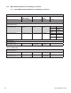
Generator Monitored Parameters
Status Off, Running, Alarm
Alarm Logical (OR) of: low oil pressure, engine over temperature, engine over speed, crank limit, over
voltage, low fuel, water intrusion, pad shear, gas hazard, test fail
Gas Hazard Indicates combustible fumes above acceptable levels (LEL)
Water Intrusion Generator compartment ooded
Pad Shear Generator has been dislocated
Enclosure Door Open or Closed
Ignition Battery Voltage Measured value for 12V generator battery. Reported to +/- 100mv resolution
Enclosure Temperature Measured temperature inside generator compartment
Low Fuel Indicates fuel level insufcient to sustain engine
Remote Test Control Start/Stop generator self test cycle
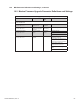
Modem Parameters
Standards “DOCSIS 2.0
EuroDOCSIS 2.0”
Tx Frequency Range “5 to 42 MHz DOCSIS, 5 to 65 MHz EuroDOCSIS”
Output Power +8 to +58 dBmV
Channel Bandwidth “6 MHz DOCSIS, 8 MHz EuroDOCSIS”
Receive Center Frequency Range “91 to 857 MHz DOCSIS, 108 to 862 MHz EuroDOCSIS”
Input Level -15 to +15 dBmV