
Instruction Manual

48 745-814-B0-001, Rev. A
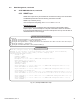
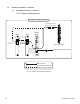
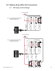
Fig. 7-6, System Interconnection Diagram
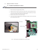
7.3.3 Front Panel Connections
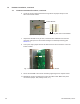
Connections
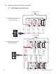
Connections with more
than one power supply
7.0 Hardware Installation, continued
7.3 XP-DSM Connections, continued
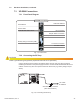
To Battery Sense Wire Harness
Communications
Port
Communications
Port
C
O
M
S
Y
S
C
O
M
S
Y
S
STAT
ALM
RDY
COM
LNK
DS
REG
RF
TMPR
C
O
M
LOCAL
XM2 XM2
“Master”
XM2
Generator (ECM)
ECM to SCM Interface
(Alpha P/N 704-709-20)
Battery String
Connector
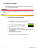
System Port
Communications Port
System Port
XP-DSM Front Panel Connections