
Instruction Manual

47745-814-B0-001, Rev. A
7.0 Hardware Installation, continued
7.3 XP-DSM Connections
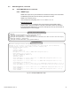
7.3.1 Front Panel Diagram
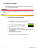
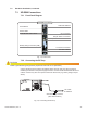
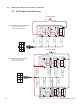
Connect the RF drop according to the diagram below. The RF drop must have a properly
installed ground block in the power supply enclosure. Recommended downstream RF level is
0 dBmV. Connect any other front panel connections at this time (e.g. battery strings, tamper
switch).
Install a grounded surge suppressor (Alpha P/N 162-028-10 or equivalent).
CAUTION!
RF Cable
to Headend
Grounded Surge Protector
(See Caution Above)
Battery
nput
Temp
Probe
Battery
Breaker
STAT
ALM
RDY
COM
LNK
DS
REG
RF
DC
TMPR
O
O
XP-DSM
Fig. 7-5, Connecting the RF Drop
7.3.2 Connecting the RF Drop
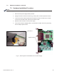
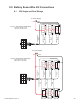
Fig. 7-4, Front Panel
XP-DSM Front Panel
Reset Button
Status LEDs
RF Connection
Cable Modem Status LEDs
Tamper Switch Connection
AlphaBus Communication Port
Battery String Connection (A/B)
Local Port Connection
RF MAC Address
CPE MAC Address