
Instruction Manual

46 745-814-B0-001, Rev. A
7.0 Hardware Installation, continued
7.2 Hardware Installation Procedure, continued
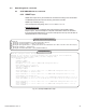
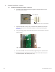
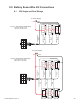
6. Locate the 18-pin jumper and insert the long side of the jumper rmly into the
side of the inverter module.
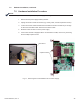
7. Unpack the XP-DSM. If not yet done, record the MAC addresses from the front
of the unit, and report it to the network manager for network provisioning (see
Section 3.1).
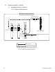
9. Secure the XP-DSM to the inverter module by tightening the two captive screws.
10. Reinstall the inverter module and reconnect the ribbon cable. Make front panel
connections (tamper, RTS, battery sense, etc.).
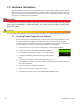
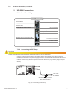
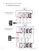
8. Line up the 18-pin jumper with the XP-DSM connector and connect the unit to the
inverter module.
Insert Long Side Into Inverter Module
Inverter Module
Fig. 7-2, The 18-pin Jumper
Fig. 7-3, Connecting the Transponder to the Inverter Module