
Instruction Manual

34 745-814-B0-001, Rev. A
6.0 Data Management, continued
6.3 SCTE-HMS MIB Alarms
The HMS discrete and analog alarms provide the capability to monitor and alarm various
power supply and environmental conditions and measurements. The alarms in the MIB tables
can be dened and set to provide a custom monitoring system.
6.3.1 SCTE-HMSCongurableAlarms
The SCTE-HMS MIB tables can be congured to send SNMP traps to a network
management system in response to certain power supply conditions. The tables
used to dene these alarms are the propertyTable and the discretePropertyTable,
which are both located in the propertyIdent MIB at OID 1.3.6.1.4.1.5591.1.1. When
an alarm condition is detected in either of these tables, an entry is created in the
alarmTable, and an alarmEvent SNMP trap is sent by the transponder to the SNMP
trap address.
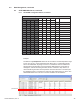
propertyTable: Analog Alarms
Each variable in this table corresponds to an analog value of the power supply. The
alarms are disabled by default, and may be enabled and congured to suit monitoring
preferences. Each entry in the propertyTable has four possible alarm threshold levels:
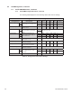
Threshold Level Denition
LOLO alarm threshold for extreme low condition
LO alarm threshold for low condition
HI alarm threshold for high condition
HIHI alarm threshold for extreme high condition
There is also a ‘Deadband’ setting used as a buffer to prevent alarm oscillation when
the analog value transitions from an alarm state to a non-alarm state. The value must
exceed the alarm threshold by the amount of the deadband value before the alarm
will clear.
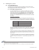
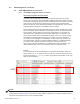
An alarm for a parameter in the table is enabled by setting its ‘alarmEnable’ bit-mask.
By setting the bits, the user can dene which threshold levels are enabled. A “1” in a
bit position indicates the threshold level is enabled. This bit mask is converted to Hex
within the table.
For example, to set an alarm for only HI level values of a parameter, then set Bit 2 to
“1”, represented by 00000100 binary, or 04 Hex. To set alarms for all threshold levels,
enable Bits 0 through 3 by setting them to “1” represented by binary 00001111, or 0F
Hex.
See the table and example on the next page.
NOTE:
• Some programs, such as MG-Soft, use a Hex notation where 0F, for example, is rendered 0x0F. There is
no difference in the binary meaning of this notation.
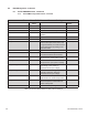
• Most of the values in the propertyTable are scaled 1/100. For example, 43V is rendered 4300. See Table
6-4.