
User guide

64
042-288-B0-001, Rev. A2
4.0 The Engine Control Module, continued
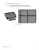
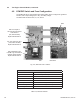
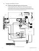
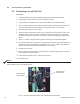
4.8 ECMDIPSwitchandFuseConguration
The ECM PCB has an eight-position DIP switch (SW5) used to congure the generator
interface, APU output voltage (AC or DC), and utility voltage.
The GRI board has three fuses, F1, F2, and F3.
F2: 12V Output to
APU Fan and Enclosure
Gas Detector
(2A, 250V Slo-Blo)
Alpha P/N 460-205-10
F3: 120/240Vac Input
to ECM Logic Transformer
(250mA, 250V Slo-Blo)
Alpha P/N 460-166-10
SW5
F1: 12V Input from APU
(2.5A, 250V Slo-Blo)
Alpha P/N 460-204-10
GRI
ECM PCB
Fig. 4-5, SW5 and Fuse Locations
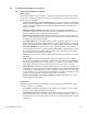
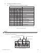
Table 4-3, Telecom Defaults
Telecom Defaults
Low DC Bus Level Default 49V (2V/cell)
High DC Bus Level Default to 57V (2.38V/cell)
Service Interval Default 100 hours
Autotest Interval Will auto set to 14 days when SW5-8 is set ON
Autotest Duration Default 10 minutes
Start Delay Default 180 seconds (3 minutes)
Shutdown Delay Default 720 seconds (12 minutes)
Over-voltage Duration Default 5 seconds