
Installation and Operation Manual Owner manual

76
745-020-B0-003, Rev. C
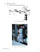
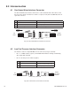
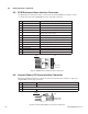
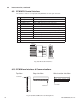
Fig. 8-5, ECM Enclosure Alarm Interface Connector
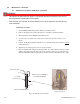
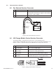
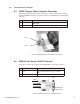
8.6 Inverter Battery DC Sense Interface Connector
ECM - Inverter Battery DC Sense Interface Connector J8. The interface control is a 3-pin (1x3
row) Mini Mate-’N’-Lok style connector.
Fig. 8-6, Inverter Battery DC Sense Interface Connector
Pin Description Function
1 Water Intrusion Sensor Contact OPEN (HIGH signal) denotes water
2 Water Intrusion common Return signal path for sensor
3 Pad Shear Sensor Contact CLOSED (LOW signal) denotes pad shear
4 Pad Shear Common Return signal path for sensor
5 Low Fuel Pressure Sensor Contact CLOSED (LOW signal) denotes low fuel
pressure (LP versions only)
6 Low Fuel Pressure Common Return signal path for sensor
7 Gas Hazard Sensor Switch Active OPEN signal denotes gas hazard (Logic HIGH)
8 Gas Hazard Power/Alarm Return signal path for sensor (Common)
9 Gas Hazard Logic Power Logic power for Logic PCB & sensor (+12VDC Fused)
10 Door Open Sensor Contact CLOSED (LOW signal) denotes door is open
11 Door Open Common Return signal path for sensor
12 No Connection
13 +12V Fused LPG fuel monitor
14 Common Return path for LPG fuel monitor
8.0 Interconnection, continued
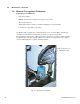
8.5 ECM Enclosure Alarm Interface Connector
The Alarm Interface Connector (J10) is connected to the Power PCBA. The interface control
is a 14-pin (2x7 row) Universal Mini Mate-’N’-Lok style male connector.
REAR
VIEW
WIRE
SIDE
J10
REAR
VIEW
Pin Description Function
1 DC Bus Sense (POS.) Output inverter battery bus – positive connection, 48 and 98VDC buses
2 No Connection
3 DC Bus Sense ( NEG.) Output inverter battery bus – positive connection, 48 and 96VDC buses
REAR
VIEW
REAR
VIEW
WIRE
SIDE
J8