
Installation and Operation Manual Owner manual

74
745-020-B0-003, Rev. C
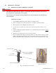
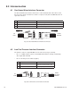
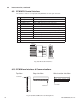
Fig. 8-1, Gas Hazard Detector Interface Connector
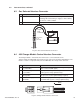
Fig. 8-2, Low Fuel Pressure Interface Connector
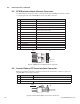
Pin Description Function
1 Gas Hazard Sensor Switch Active OPEN signal denotes gas hazard (Logic HIGH)
2 Gas Hazard Power/Alarm Common Return signal path for sensor
3 Gas Hazard Logic Power +12VDC Fused Logic Power for Logic PCB & sensor
8.0 Interconnection
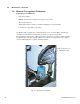
8.1 Gas Hazard Alarm Interface Connector
The Gas Hazard Detector Interface Connector is connected between the wire harness and
detector unit as shown. The interface control is a 3-pin (1x3 row) Universal Mini Mate-’N’-Lok
style male connector.
REAR
VIEW
REAR
VIEW
TO
ECM
FROM
SENSOR
Rear view, wire side
TO
ECM
FROM
LOW
FUEL
SENSOR
Rear view, wire side
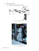
8.2 Low Fuel Pressure Interface Connector
The interface control is a 2 pin Mini Mate-'N’-Lok connector (near gas solenoid):
• Pin 1 = +12VDC activates (opens) solenoid ONLY when APU is running. Controlled by
APU engine ON command
• Pin 2 = Low fuel pressure switch (negative)
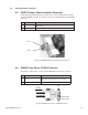
Pin Description Function
1 Low Fuel Pressure Sensor Contact Closed (LOW signal) denotes Low
Fuel Pressure (LP Versions only)
2 Low Fuel Pressure Common Return signal path for sensor