
Installation and Operation Manual Owner manual

48
745-020-B0-003, Rev. C
4.0 The Engine Control Module, continued
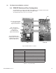
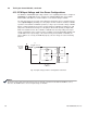
4.8 ECM DIP Switch and Fuse Confi guration, continued
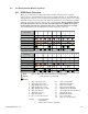
Table 4-4, DIP Switch Settings
Programming parameters that affect the Autotest feature via status monitoring will override this switch setting.
To reset factory defaults, turn all DIP switches off, power up the ECM (plug in AC line sense) for 10 seconds,
remove power, then reset DIP switches.
ON
1
2
3
45678
Interface
Output Voltage Confi guration
Input Voltage Confi guration
Engine Start/Run Signal
Enable Autotest
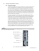
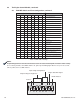
Fig. 4-7, SW5 Settings
NOTE:
ECM SW5 Settings Meaning
1 2 3 4 5 6 7 8 1 = ON, 0 = OFF
0
Non standard GRI interface
(7.5kW Series)
1 Standard GRI interface
000
Invalid output voltage configuration
001
24VDC Output
010
36VDC Output
011
48VDC Output
100
96VDC Output
101
120VDC Output
110
208VDC Output
111
240VDC Output
00
Invalid input voltage configuration
10
120AC input
01
208 3-phase input
11
240VAC input
00
No effect
10
No effect
10
ECM Drives starter with the "Engine Start"
Signal.
11
"Engine Start" Signal becomes
"Engine Run" and is held low by ECM
0
Autotest turned OFF.*
1
Autotest sequence enabled with 14-day test
interval