
Installation and Operation Manual Owner manual

46
745-020-B0-003, Rev. C
4.0 The Engine Control Module, continued
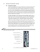
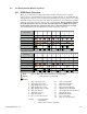
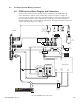
4.7 Connecting the Alarm and Control Connections
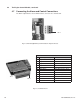
The Alarm output interface and communications connectors are shown below.
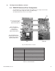
Fig. 4-4, RS-488 (AlphaBus) Communications Input Connector
Pin 1
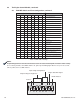
Fig. 4-5, Terminal Block 1
Terminal Block 1
Pin Alarm Signal Description Alarm Active State
1 Engine Run Common N/A
2 Engine Run Closed with respect to Pin 1
3 Engine Run Open with respect to Pin 1
4 Major Alarm Common N/A
5 Major Alarm Closed with respect to Pin 4
6 Major Alarm Open with respect to Pin 4
7 Minor Alarm Common N/A
8 Minor Alarm Closed with respect to Pin 7
9 Minor Alarm Open with respect to Pin 7
10 Not used Not used
11 Not used Not used
12 Not used Not used
Pin 1
TB 1