
Installation and Operation Manual Owner manual

745-020-B0-003, Rev. C
35
3.0 Installation, continued
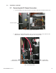
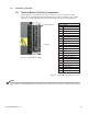
3.9 Terminal Block 2 (AC Line) Connections
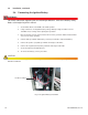
Terminal Block 2 is located in the rear of the enclosure, next to the convenience outlet.
Connect the user-supplied wiring using a #1 fl at-head screwdriver. Strip wires 3/8" (9.5mm)
and torque to 7 in-lbs (0.8 Nm). Refer to the table and photo below for alarm defi nitions.
Terminal Block 2
Pos # Function
23 Major Alarm NO
22 Major Alarm NC
21 Major Alarm Com
20 *Special Use
19 Alarm Bypass Com
18 Alarm Bypass NO
17 Alarm Bypass NC
16 Eng Run Com
15 Eng Run Com NO
14 Eng Run Com NC
13 Minor Alarm NO
12 *Special Use
11 Minor Alarm COM NO
10 Door NO
9 Door COM
8 LPG Monitor PWR (-12V)
7 LPG Monitor PWR (+12V)
6 AC Line Fail NC
5 AC Line Fail NO
4 AC Line Fail COM
3 AC Input Ground
2 AC Input Neutral
1 AC Input Line
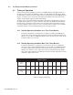
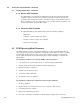
Fig. 3-11, Terminal Block 2 (TB2)
Table 3-1, Terminal Block 2 (TB2) Connections
Terminal Block 2
Position 1
*For customers requiring Normally Closed (NC) logic minor alarm, make connections to TB2 positions 12 and
20.
NOTE: