AlphaGen™ 7.5kW Generator Set Installation and Operation Manual PN-6x-T 7.
Alpha Technologies Power ®
AlphaGen PN-6x-T 7.5kW 48VDC Telecom Generator Installation and Operation Manual 745-020-B0-003, Rev. C Effective Date: January, 2006 Copyright © 2006 Alpha Technologies, Inc. member of The GroupTM NOTE: Photographs contained in this manual are for illustrative purposes only. These photographs may not match your installation. NOTE: Operator is cautioned to review the drawings and illustrations contained in this manual before proceeding.
Table of Contents Safety Notes ......................................................................................................................... 8 1.0 System Overview .................................................................................................... 13 1.1 System Diagram ............................................................................................ 14 1.2 Natural Gas System Block Diagram .............................................................. 15 1.
Table of Contents, continued 5.0 6.0 7.0 8.0 4.8 ECM DIP Switch and Fuse Configuration ...................................................... 47 4.9 ECM Interface Block Diagram and Connectors ............................................. 49 4.10 ECM Input Voltage and Line Sense Configurations ....................................... 50 4.11 ECM Self-test ................................................................................................. 51 4.12 Maintenance Functions .......................
List of Figures and Tables Fig. 1-1, PN-6x-T Generator and Enclosure (operator’s side) ............................................. 13 Fig. 1-2, System Diagram .................................................................................................... 14 Fig. 1-3, Arrangement of Metered, Nominal Pressure (1-2psi) Natural Gas System........... 15 Fig. 1-4, Excess Flow Valve ............................................................................................... 15 Fig.
List of Figures and Tables, continued Fig. 5-1, Generator Set Master Switch and Run/Auto/Stop (RAS) Switch .......................... 54 Fig. 6-1, Ignition Battery Charger LED ................................................................................ 59 Fig. 6-2, Wiring for ECM, Ignition Battery Charger, and Ignition Battery ............................. 59 Fig. 7-1, Air Filter Removal .................................................................................................. 62 Fig.
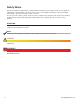
Safety Notes Review the drawings and illustrations contained in this manual before proceeding. If there are any questions regarding the safe installation or operation of the system, contact Alpha Technologies or the nearest Alpha representative. Save this document for future reference. To reduce the risk of injury or death, and to ensure the continued safe operation of this product, the following symbols have been placed throughout this manual. Where these symbols appear, use extra care and attention.
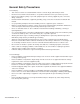
General Safety Precautions To avoid injury: • This enclosure and its associated hardware must be serviced only by authorized personnel. • Enclosure must remain locked at all times, except when authorized service personnel are present. • Remove all conductive jewelry or personal equipment prior to servicing equipment, parts, connectors, wiring, or batteries. • Read and follow all installation, equipment grounding, usage, and service instructions included in this manual.
Battery Safety Notes WARNING! Lead-acid batteries contain dangerous voltages, currents and corrosive material. Battery installation, maintenance, service, and replacement must only be performed by authorized personnel. Chemical Hazards Any gelled or liquid emissions from a valve-regulated lead-acid (VRLA) battery contain dilute sulfuric acid, which is harmful to the skin and eyes. Emissions are electrolytic, and are electrically conductive and corrosive.
Battery Maintenance Guidelines The battery maintenance instructions listed below are for reference only. Battery manufacturer’s instructions for transportation, installation, storage, or maintenance take precedence over these instructions. • • • • • • • • To prevent damage, inspect batteries every 3 months for: Signs of battery cracking, leaking or swelling. The battery should be replaced immediately by authorized personnel using a battery of the identical type and rating. Signs of battery cable damage.
Auxiliary Power Unit (APU) Notes 12 • When the engine is stopping, a small amount of unburned fuel may be present. Fans are used to expel these fumes from the enclosure, but fumes may be detected outside the enclosure for a short period of time after engine shutdown. This is a normal condition and does not present a hazard. • Most utilities add a chemical agent to the gas which produces a strong odor so leaks can be detected before they reach a dangerous or explosive level.
1.0 System Overview The AlphaGen PN-6x-T curb side generator system is designed to power outside plant communication networks. Every AlphaGen system incorporates industry leading power technology, including natural gas or propane fueling, exclusive audible noise baffling, remote status monitoring features, and a durable, weather resistant enclosure. The procedures in this document describe the installation, operation and maintenance of the PN-6x-T generator and enclosure.
2 4 3 1 0 ECM ECM TB1-4 TB1-9 6 8 7 BLACK ORANGE GREEN NO NC COM OUTPUT CB AUX SW DOOR SW DOOR SW GAS HAZARD SENSOR 1 23 2 1 RED BLACK BLACK WHITE WHITE WHITE YELLOW COM L N NC NO AC FAIL RELAY TB2-2 TB2-1 TB2-8 TB2-7 ORANGE MAJOR MAJOR MAJOR MINOR ALM ALARM ALARM ALARM ALARM BY NC COM NC NO COM COM ALM BY NO ALM BY NC ENG RUN COM ENG RUN NO ENG MINOR MINOR MINOR Door RUN ALARM ALARM ALARM NO NC NO NO NC COM Door COM LPG ( -) AC/ FAIL NC AC/ FAIL NO AC/ FAIL COM AC G
1.0 System Overview, continued 1.2 Natural Gas System Block Diagram CAUTION! Do not include the generator system as part of a local gas piping system test. Damage to the generator pre-regulator may result. The generator system is pressure tested in accordance with NFPA standards prior to shipment. ENGINE Demand Low-pressure Regulator CONTROLS 14" WC (max.) APU Enclosure CONTROL Solenoid S Engine must have 7" to 11" WC and 156 cubic feet/Hr.
1.0 System Overview, continued 1.3 Liquid Propane System Block Diagram LP PROPANE - VAPOR WITHDRAWAL BLOCK DIAGRAM ENGINE DEMAND CONTROLS LOW PRESSURE REGULATOR 8oz MAX S 11"WC APU ENCLOSURE SENSOR 11"WC OUTLET SOLENOID CONTROL LOW FUEL ALM LOW FUEL PRESSURE SWITCH PROPANE POST-REG PROPANE ENCLOSURE LPG TANK Fig. 1-5, LP Propane Vapor Withdrawal Block Diagram 16 745-020-B0-003, Rev.
1.0 System Overview, continued 1.4 Specifications System Specifications Specification System Size Height: 39.0" (57" with optional pedestal) Width: 39.25" Depth: 24" Weight: 338 lbs (370 lbs with optional pedestal) Acoustic 70.3 dBa @ 10 feet, (100% load) DC Electrical Noise (PN-6x-T) RF: <100mV RMS in any 3kHz Band, 3kHz to 20MHz Broadband: <250mV Pk to Pk Voice Freq. Noise: Less than 56dBnrc Gas Inlet Pressure 0.5-2 psi NOTE: Contact Alpha Technologies for low pressure operation below 0.
1.0 System Overview, continued 1.4 Specifications, continued Engine Specifications 18 Specification Manufacturer Kohler Generator Set Specification Make/model CH20 Manufacturer: Kohler Cycle 4 Dimensions (in/mm): Compression Ratio 8:5:1 21.5"L x 20"W x 21.8"H/ 546 x 508 x 554 Displacement, cu. in. (cc) 38 (624) Weight (lb/kg): 190/86 Rated Horsepower (using natural gas fuel) 13.1 Rated* kW: 7.5 52 ± 0.
2.0 Site Preparation 2.1 2.2 Site Considerations • Where possible, select a site that is above the 100 year flood plain, and away from houses. • Place in a shaded location to minimize the effects of solar loading. • Avoid locating the enclosure where it is an obstruction and would inhibit visibility. • Locate the enclosure away from sprinkler systems or other sources of forced water.
2.0 Site Preparation, continued 2.2 Acoustics, continued The design of the engine-generator system should direct a majority of the operational noise toward the street and away from residences that may be located behind the curb side system. This strategic cabinet design and placement within the community can minimize nuisance noise and city ordinance issues. House 20 Feet, (64 dBa) Engine-Generator Street 50 Feet (56 dBa) House Fig.
2.0 Site Preparation, continued 2.3 Enclosure Impact Protection The National Fire Protection Agency (NFPA) requires that equipment utilizing natural gas or liquid propane be protected, based on good engineering practices, in areas where vehicle traffic is normally expected at that location. The required protection is based on the anticipated speed of the vehicles operated in that area. The NFPA does not provide specific guidelines for when protection is needed or the nature of the protection.
2.0 Site Preparation, continued 2.3 Enclosure Impact Protection, continued 2.3.1 Generator Protection, Vehicular Areas, continued The remote located natural gas meter shown below may require two to four bollard posts depending on location, site survey, and traffic pattern. This is a typical installation design, with gas meters supported by dual risers and located near the cabinet (within 25 feet).
2.0 Site Preparation, continued 2.4 Natural Gas Meter Configurations The gas utility should have the meter installed prior to generator arrival. Meter configurations must comply with local codes. The illustrations provided are for illustrative purposes only. NATURAL GAS METER STREET REGULATOR MANUAL SHUTOFF OPTIONAL HIGH PRESSURE EXCESS FLOW VALVE STREET PRESSURE Fig.
2.0 Site Preparation, continued 2.5 Liquid Propane Systems For systems using liquid propane, the end user must provide a suitable LP tank. Manual Shutoff User-provided LP Tank Fig. 2-7, Liquid Propane Setup 24 745-020-B0-003, Rev.
2.0 Site Preparation, continued 2.6 Grounding Requirements The ground rod system is typically used in remote applications where the generator is located away from the power supply enclosure and exposed to lightning strikes, or coincidental surges. The wiring interface between the DC Genset and system carries a system ground to ensure common ground between both cabinets and communication devices. The remote APU cabinet ground rod serves only as an alternate discharge path.
3.0 Installation Prior to installation verify the following: • All necessary grounding rods and materials are in place. • Utility power was run to site in accordance with the NESC (National Electric Safety Code). • Obtained local safety practices for working with high-voltage systems. • Gas piping, hardware, supports, and other gas carrying components to the pad location conform to NFPA standard and local requirements.
3.0 Installation, continued 3.1 Transportation The enclosure as shipped contains the Auxiliary Power Unit (APU) and, therefore, is heavy (approximately 338 lbs). A safe means of transportation to the site and unloading the enclosure must be considered. Do not transport, lift, or place the unit on any surface unable to fully support its weight. CAUTION! The ignition battery MUST NOT be installed until the enclosure is set in place at its permanent location. The system is shipped bolted to a pallet.
3.0 Installation, continued 3.2 Lifting Procedure The enclosure is lifted via four lifting plates included with the generator. The lifting plates are attached to the cabinet with 1/4-20 x 3/8" stainless steel SAE J429 Grade 8 hex-head bolts, torqued between 80 and 90 in-lbs. WARNING! To prevent injury or death, do not walk, or allow personnel to walk, beneath the suspended unit. Use steel-toe work shoe protection. Use hard hats at all times during this procedure.
3.0 Installation, continued 3.3 Enclosure Installation Procedure 1 CAUTION! Position the enclosure above the concrete pad and slowly lower it into position over the pad’s 3/8" (or 1/2") anchor or J-bolts. A 25+ year vapor barrier MUST be used between the concrete and enclosure base to inhibit moisture ingress, and to prevent possible corrosion caused by metal to concrete contact.
3.0 Installation, continued 3.4 Enclosure Grounding ATTENTION: It is the responsibilty of the system installer to verify applicable grounding requirements, and to ensure that system grounding complies with all state, local, or regional requirements. Run the chassis and earth grounding wires through the one-inch opening in the bottom of the generator enclosure. Using a 7/16" nutdriver or socket, secure the ground leads to the grounding stud located on the enclosure wall. See Fig. 3-5 below.
3.0 Installation, continued 3.5 Natural Gas Utility Fuel Hookup These general instructions apply to either remote or collocated systems. • Connection to the utility fuel line is made using a 3/4" shear point union, 1/2" black iron pipe, and the appropriate pipe thread sealant suitable for use with natural gas or propane vapor. • Use approved pipe thread sealant on all fuel line connections (except flare fittings). • Thoroughly check the fuel system for vapor leaks.
3.0 Installation, continued 3.6 Liquid Propane Utility Fuel Hookup • Connection to the LP fuel line is made using a 3/4" shear point union, 1/2" black iron pipe, and the appropriate pipe thread sealant suitable for use with propane vapor. • Approved pipe thread sealant must be used on all fuel line connections (except flare fittings). • Thoroughly check the fuel system for vapor leaks.
3.0 Installation, continued 3.7 Connecting the DC Output Connection 1. Locate and remove the safety shroud. The shroud is held in place with two thumbscrews. Shroud Location Fig. 3-8, DC Output Safety Shroud 2. Strip the user-supplied DC load wires 3/4". Loosen the 3/16" Allen screws and insert the DC load wires. Torque to 120 in-lbs and replace the safety shroud. Negative DC Load Connection Positive DC Load Connection Fig, 3-9, DC Output Block 745-020-B0-003, Rev.
3.0 Installation, continued 3.8 Connecting the Ignition Battery WARNING! For further information regarding the safe handling of batteries, refer to the Battery Safety Notes at the beginning of this manual. 1. Set the RAS switch on the ECM to the STOP position. 2. Using a voltmeter, check ignition battery voltage. Battery voltage should be at least 12.5VDC. If low, recharge before placing into operation. 3.
3.0 Installation, continued 3.9 Terminal Block 2 (AC Line) Connections Terminal Block 2 is located in the rear of the enclosure, next to the convenience outlet. Connect the user-supplied wiring using a #1 flat-head screwdriver. Strip wires 3/8" (9.5mm) and torque to 7 in-lbs (0.8 Nm). Refer to the table and photo below for alarm definitions. Terminal Block 2 Terminal Block 2 Position 1 Fig.
3.0 Installation, continued 3.10 Final Inspection Checklist CAUTION! Alpha recommends setting the ECM Run/Auto/Stop (RAS) switch to the STOP position before initially powering up the ECM. This allows the operator to control the START and STOP functions of the APU until the system is set up. This also prevents the APU from starting unexpectedly. Once the installation has been completed verify the following: 1. Engine oil at proper level. 2. All electrical connections securely made. 3.
4.0 The Engine Control Module The Engine Control Module (ECM) controls and monitors the generator’s Auxiliary Power Unit (APU). The ECM is a two part assembly made up of the ECM Printed Circuit Board (ECM PCB) and the Generator Remote Interface (GRI) board. The ECM PCB/GRI assembly is mounted to the top of the generator housing, to the left of the ignition battery. The GRI is attached to the ECM PCB via three ribbon cables. The GRI powers the ECM and steps down high voltage.
4.
4.0 The Engine Control Module, continued 4.1 Theory of Operation Under normal operating conditions (no alarms) the ECM Run-Auto-Stop (RAS) switch is in the AUTO (center) position. The ECM has control of the APU while in the Auto mode. When the RAS switch is switched from the STOP position to the AUTO position the ECM will run the APU for one minute, after a short delay. This indicates the ECM is in the Auto mode and is capable of starting and stopping the APU automatically.
4.0 The Engine Control Module, continued 4.1 Theory of Operation, continued 4.1.3 Normal APU Shutdown The ECM initiates a normal APU shutdown when the AC line is within normal limits, the DC bus alarm is not active, the 12 minute cool-down period has elapsed, and the Engine Run command is not active. The ECM continues to run the APU until the above conditions are met or a major alarm occurs. The APU will run a minimum of 30 minutes if started due to low DC Bus voltage. 4.1.
4.0 The Engine Control Module, continued 4.2 ECM Operating Mode Summary, continued The following conditions cause immediate engine shutdown: 1. Manual engine stop switch is activated. 2. Software engine stop switch is received. 3. Any of the following engine alarms become active: • Low oil • Engine over-temperature • Low fuel • Over-speed • Over-crank • Over-voltage 4. Any of the following system alarms become active: 4.
4.0 The Engine Control Module, continued 4.4 Control Functions The Run-Auto-Stop (RAS) switch controls the Auxillary Power Unit (APU). Typically the RAS switch is in the AUTO position so the ECM has control of the generator. When the RAS is not in the AUTO position a minor alarm is displayed. The STOP position is used to stop or prevent APU operation during maintenance.
4.0 The Engine Control Module, continued 4.5 Alarm Classifications Major Alarms: A major alarm indicates a critical failure or situation that causes the system to go off-line. Major alarms cause the engine to shutdown immediately and generally prevent further operation. Most major alarms are latched by the ECM. Placing the RAS switch to the STOP position for three seconds, then switching back to AUTO clears any latched alarms and starts the generator (if the cause of the alarm has been corrected).
4.0 The Engine Control Module, continued 4.5 Alarm Classifications, continued Minor Alarms: Minor alarms indicate a system fault which, though not indicative of imminent system failure or shutdown, requires service attention before the condition worsens. A site check by service personnel is recommended. • Control Fail (Latching – after five activations): Indicates a control failure between the ECM and the generator set. Typically this means the engine did not start or stop when commanded to do so.
4.0 The Engine Control Module, continued 4.6 ECM Alarm Overview Alarms are indicated in three ways: ECM LEDs, RS-485 communications, and alarm contact closures on the ECM transponder interface. Alarm indications on the ECM LEDs are displayed by pressing the service reset button momentarily. Pressing the service reset switch again will reveal the next alarm in the list. When the alarm list has been exhausted, all LEDs will flash several times and then return to their normal functions.
4.0 The Engine Control Module, continued 4.7 Connecting the Alarm and Control Connections The Alarm output interface and communications connectors are shown below. Pin 1 Fig.
4.0 The Engine Control Module, continued 4.8 ECM DIP Switch and Fuse Configuration The ECM PCB has an eight-position DIP switch (SW5) used to configure the Generator Interface, APU output voltage (AC or DC), and utility voltage. The GRI board has three fuses, F1, F2, and F3. SW5 F1: 12V Input from APU (1.
4.0 The Engine Control Module, continued 4.8 ECM DIP Switch and Fuse Configuration, continued ECM SW5 Settings 1 2 Meaning 3 4 5 6 7 8 1 = ON, 0 = OFF Non standard GRI interface (7.
4.0 The Engine Control Module, continued 4.9 ECM Interface Block Diagram and Connectors The Generator Remote Interface provides power conditioning to the ECM PCB, and connection between cabinet sensors and the APU control. The interface supplies all necessary signals, alarms, logic power, and analog voltages required for telemetry at the head end.
4.0 The Engine Control Module, continued 4.10 ECM Input Voltage and Line Sense Configurations The ECM has 120/240VAC input voltage and line sense capability that must be configured separately. The ECM PCB must be configured for 120/208/240VAC line sense via DIP Switch SW5-5 and SW5-6 as shown in Table 4-7. The default setting is 120VAC. The logic transformer (T1) located on the GRI power board must also be configured for the correct input voltage by installing zero ohm jumpers R1-R4.
4.0 The Engine Control Module, continued 4.11 ECM Self-test NOTE: The Telecom Power Monitor (TPM) option is required to access all ECM programmable parameters. These parameters cannot be changed without the TPM. Generator testing consists of starting and running the generator for a programmable period of time (the default test duration is 10 minutes). Generator testing can be initiated in three ways: 1. The ECM is configured to periodically run an automatic test. 2.
4.0 The Engine Control Module, continued 4.11 ECM Self-test, continued The following programmable, internal ECM variables control automatic self-tests. • Autotest Interval: This feature represents the number of days between automatic tests. Programming this variable to 0 disables the automatic test feature. • Autotest Countdown: This countdown timer is monitored by the ECM to determine when the next automatic test is due.
5.0 Turn-up and Test 5.1 Appearance and Condition of Components Prior to applying power, open each door of the enclosure. Observe and note the condition of the following: 5.2 • Doors and locking mechanisms • Seals • Door intrusion switches System Preparation The following procedure involves starting and stopping the engine using the Engine Control Module (ECM).
5.0 Turn-up and Test, continued 5.3 Performing a Local APU Test Procedure: 1. Locate the ECM and set the Run/Auto/Stop (RAS) switch to the STOP position. 2. Verify ignition battery and AC line sense connection to ECM. 3. Verify all alarms on ECM are OFF, except Tamper Alarm & Auto Mode Disabled. 4. Remove gas port plug from input side of demand regulator, install brass manometer port connection fitting and connect manometer to fitting (see Section 7-9 for details). 5.
5.0 Turn-up and Test, continued 5.3 Performing a Local APU Test, continued 9. If necessary, adjust the pre-regulator or dual regulator (located on gas bottle assembly for propane) by removing regulator cap and adjusting for 11" ± 1" of water column pressure. Perform under NO-LOAD condition (see Section 7.9 for details). 10. Set RAS switch to Stop. 11. Remove brass manometer fitting and reinstall plug to demand regulator input monitoring port using approved pipe sealant. 12.
5.0 Turn-up and Test, continued 5.4 Generator System Sensor Verification The ECM has a built-in self-test feature. Each time the ECM’s RAS (Run-Auto-Stop) switch is placed in the AUTO position, a one minute self-test is performed and any failures are reported as major or minor alarms. Latched alarms can be reset after the fault has been cleared by placing the RAS switch to the STOP position for three seconds and then back to the AUTO position. 5.4.1 Enclosure Alarm Verification 1.
5.0 Turn-up and Test, continued 5.4 Generator System Sensor Verification, continued 5.4.2 AC and DC Line Sense Verification The ECM monitors the AC line and DC bus status to determine when to start and stop the APU. In the event of an extended power outage or low battery bus voltage the ECM will start the APU. The following test will verify these functions. 1.
6.0 Operation 6.1 Normal Operating Condition Under normal operating conditions (no alarms) the ECM’s RAS switch is in the AUTO position. The ECM has control over the APU while in Auto mode. Each time the RAS switch is moved from the STOP position to the AUTO position, the ECM, after a short delay, runs the APU for one minute. This indicates that the ECM is in the Auto mode, and is capable of starting and stopping the APU automatically.
6.0 Operation, continued 6.2 Alpha Ignition Battery Charger Overview The Alpha Ignition Battery Charger (Alpha P/N 744-870-21)) keeps the ignition battery charged to start the Auxiliary Power Unit (APU) in the event of an extended power outage. The charger is active when the yellow LED on the face of the unit is lit. When the generator starts, the Alpha Ignition Battery Charger (IBC) shuts off and internal engine charger takes over ignition battery charging.
7.0 Maintenance The engine/alternator requires maintenance at regular intervals to remain reliable and ready to provide backup power when needed. Please refer to the following table for general maintenance guidelines. For specific recommendations regarding maintenance intervals, please refer to the supplied engine manufacturer’s operator’s manual.
7.0 Maintenance, continued 7.1 Servicing the APU Required Tools and Equipment: • Phillips screwdriver • 10mm socket wrench • 3/8" open-end wrench • Digital Voltmeter (DVM) capable of displaying true RMS • Battery operated frequency counter (or DVM with this function) Prior to Performing Maintenance Activities: 1. For routine engine maintenance procedures, refer to the Kohler Power Systems COM7.5 Operation Manual included with your generator. 2.
7.0 Maintenance, continued 7.2 Filter Cleaning The air intake filter (Alpha P/N 561-216-10) is located inside the air intake vent on the side of the enclosure. CAUTION! Failure to keep the filter clean, or using improperly installed filters, may cause system failure due to dirt buildup or lack of cooling air. Equipment failures caused by filter blockage, incorrect filter substitution, or dirt ingress due to clogged or improperly installed filters are not covered under warranty.
7.0 Maintenance, continued 7.3 Pad Shear Magnetic Switch Replacement Required Tools: #2 Phillips screwdriver 1. Unlock and remove rear enclosure door. 2. Locate the Pad Shear switch on the left side of the enclosure floor. 3. Remove the two screws holding the switch bracket to the floor. 4. Disconnect electrical connections, and remove the switch assembly (inset). 5. Unbolt the switch from the bracket, and replace. 6. Reinstall in reverse order. NOTE: Electrical connections are NOT polarized.
7.0 Maintenance, continued 7.4 Replacing Gas Hazard Sensor 1. Unlock and remove the front enclosure door. 2. Locate and remove the gas hazard sensor. The gas hazard sensor is located to the left of the ECM cage and above the hour meter. It is attached to the sheet metal with a hook and loop fastener. Disconnect the wire harness. 3. Verify the selector switch of the new sensor is in the proper position for your fuel source. 4. Reconnect wire harness. 5. Place new sensor on the hook and loop pad.
7.0 Maintenance, continued 7.5 Replacing Ignition Battery Charger Module Assembly Required Tools: #2 Phillips screwdriver The 48VDC charger module is located above the ECM housing. 1. Disconnect the connectors from the front of the module. 2. Remove the Phillips screw holding the front of the charger to the ECM housing. 3. The back of the charger is held in place by a tab that fits into a slot on to the ECM housing. Slide the charger free and lift it out of the enclosure. Remove Screw Fig.
7.0 Maintenance, continued 7.6 Replacing Engine Control Module 1. Set RAS to STOP. 2. Turn off 200A DC circuit breaker. 3. Disconnect wire harnesses on ECM top to bottom. 4. Release the ECM captive latch and slide the ECM out of its housing. 5. Check new ECM DIP switch configuration per Table 4.4 on page 48. 6. Verify 120V/240V jumpers in the 120V position. 7. Install new ECM card. Verify card edges are in rails and latch card in place. 8. Verify RAS is OFF. 9. Reconnect wire harnesses top to bottom. 10.
7.0 Maintenance, continued 7.7 Fuel Conversion – Natural Gas to LP 7.7.1 Pre-regulator Removal with Low Pressure Switch Installation WARNING! The following procedure must only be performed by qualified personnel. To prevent injury, disable generator and disconnect gas supply prior to beginning the gas conversion procedure. Required Tools: 7/8" open-end wrench In this procedure, the pre-regulator is removed, and a low pressure switch is installed in its place.
7.7 Fuel Conversion – Natural Gas to LP, continued 7.7.2 Switching the LP Port to the NG Port WARNING! The following procedure must only be performed by qualified personnel. To prevent injury, disable generator and disconnect gas supply prior to beginning the gas conversion procedure. Required Tools: • 7/8" open-end wrench • NFPA-approved pipe sealant In this procedure, the gas inlet hose is switched from the LP port to the NG port. Reverse this process if converting from Natural Gas to Propane. 1.
7.0 Maintenance, continued 7.8 Gas Solenoid Replacement Procedure Required Tools and Materials: • Crescent wrench • Pipe thread compound • Leak detector compound (soapy water) Two people are required to perform this procedure. To replace the fuel solenoid, the entire regulator package must be replaced. 1. Ensure the fuel supply is disconnected from the input regulator. 2. Remove the pre-regulator at the connection to the right of the solenoid. 3. Remove the flexible hose from the load block. 4.
7.0 Maintenance, continued 7.9 Maxitrol Pre-regulator Calibration Required Tools and Materials: • Flat Tip Screwdriver • DWYER # 1212 water column (0-16") gas pressure test kit • Allen head wrench set • NFPA-approved pipe sealant (i.e. Megaloc Multipurpose Thread Sealant) • Leak detector compound (soapy water) The Maxitrol 325-3 regulator has a maximum inlet pressure of 10 PSI. Alpha Technologies recommends all installations range between 1-2 PSI for consistent of gas flow.
7.0 Maintenance, continued 7.9 Maxitrol Pre-regulator Calibration, continued Fig. 7-12, Pre-regulator Calibration Fig. 7-13, Secondary Demand Regulator 745-020-B0-003, Rev.
7.0 Maintenance, continued 7.9 Maxitrol Pre-regulator Calibration, continued WARNING! • No matches or open flame or sparks. Use caution whenever working in the area to prevent possible combustion of fuel vapors. • Leak Hazard: Use caution whenever working in the area to prevent and correct any leaks detected. Calibration Procedure: 1. Set the ECM Run/Auto/Stop (RAS) switch to the STOP position. 2. Remove the Allen-head screw located on the secondary or demand regulator. 3.
7.0 Maintenance, continued 7.9 Maxitrol Pre-regulator Calibration, continued 6. Verify the DWYER # 1212 manometer reads 5-1/2" above the “0” mark, and 5-1/2" below the “0” mark. This equals 11" water column of pressure. Adjust the Maxitrol regulator in a clockwise direction to increase pressure, and in a counterclockwise direction to decrease pressure. CAUTION! Do not bottom out the regulator adjust screw. If you cannot get a reading, retest the inlet pressure to the Maxitrol gas package. 7.
8.0 Interconnection 8.1 Gas Hazard Alarm Interface Connector The Gas Hazard Detector Interface Connector is connected between the wire harness and detector unit as shown. The interface control is a 3-pin (1x3 row) Universal Mini Mate-’N’-Lok style male connector.
8.0 Interconnection, continued 8.3 Gas Solenoid Interface Connector Pin Description Function 1 Gas Solenoid +12V +12VDC supplied to Gas Solenoid only when APU is ON (Running). APU Shuts OFF gas supply to cabinet during any fail safe or fault condition. 2 Gas Solenoid Common Return path for Gas Solenoid. Vapor Fuel Solenoid Connection is not polarized FROM APU Fig. 8-3, Gas Solenoid Interface Connector 8.
8.0 Interconnection, continued 8.5 ECM Enclosure Alarm Interface Connector The Alarm Interface Connector (J10) is connected to the Power PCBA. The interface control is a 14-pin (2x7 row) Universal Mini Mate-’N’-Lok style male connector.
8.0 Interconnection, continued 8.7 48VDC Charger Control Interface Connector The Battery Charger Control Interface Connector is connected between the charger module and ECM as shown. The interface control is a terminal block 2-position plug-in connector. Pin Description Function 1 Control Positive Connects pin 1 & 2 together, turning the Charger ON, i.e. Closed (LOW signal) 2 Control Negative Charger control common return Pin 1 Pin 2 Fig. 8-7, 48VDC Charger Control Interface Connector 8.
8.0 Interconnection, continued 8.9 ECM APU Control Interface The interface control is a 12-pin (2x6 row) Mini Mate-’N’-Lok style connector. Pin Description Function 1 +12V Ignition Battery Ignition Battery Fused 12V from APU 2 Neg. Ignition Battery Ignition Battery Negative from APU 3 Low Oil Pressure Active LOW signal denotes low oil pressure. 4 Over-temp Active LOW signal indicates Over-temp. 5 Start Command Active LOW from ECM activates APU Start relay.
Power Alpha Technologies ® Alpha Technologies 3767 Alpha Way Bellingham, WA 98226 USA Tel: +1 360 647 2360 Fax: +1 360 671 4936 Web: www.alpha.com Alpha Technologies Ltd. 4084 McConnell Court Burnaby, BC, V5A 3N7 CANADA Tel: +1 604 430 1476 Fax: +1 604 430 8908 Alpha Technologies Europe Ltd.